Information body assy, injecti
Rating:
Scheme ###:
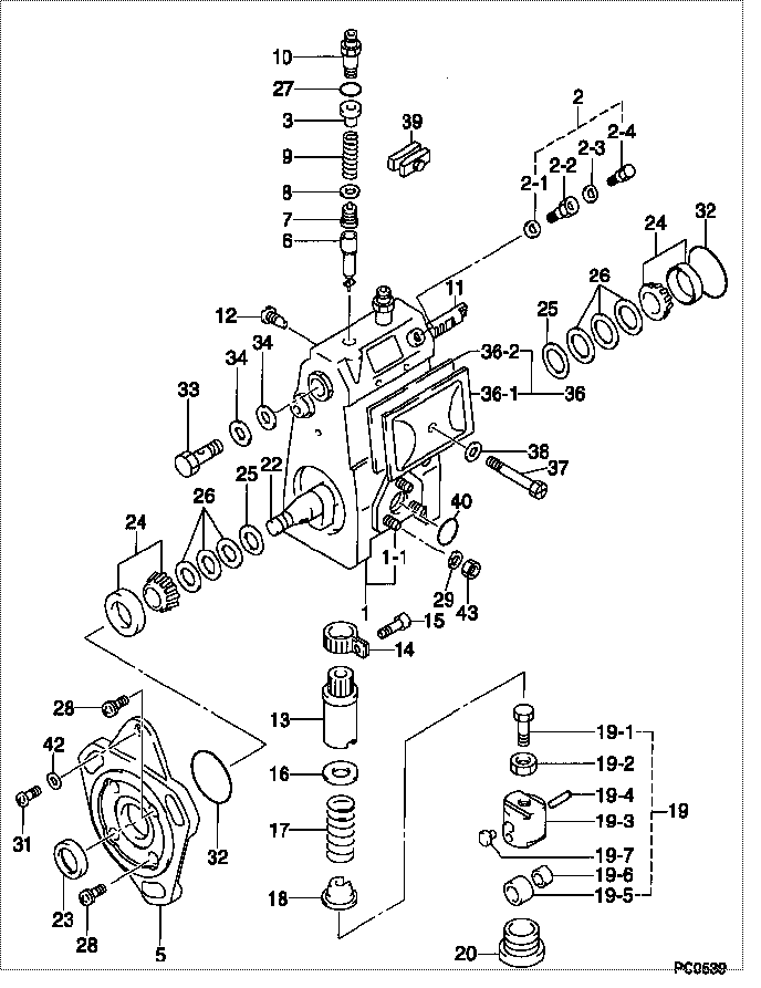
| 000. | [01] | 09010-01840 | BODY ASSY, INJECTI | 09010-01840 |
| 001. | [01] | 19011-01090 | HOUSING KIT, INJEC | 19011-01090 |
| 001-001. | [03] | 94904-30010 | BOLT, STUD | 94904-30010 |
| 002. | [01] | 09024-00010 | BLEEDER SUB-ASSY, | 09024-00010 |
| 002-001. | [01] | 09024-10010 | WASHER, AIR BLEEDE | 09024-10010 |
| 002-002. | [01] | 09024-20010 | NIPPLE, AIR BLEEDE | 09024-20010 |
| 002-003. | [01] | 09024-30030 | PACKING, AIR BLEED | 09024-30030 |
| 002-004. | [01] | 09024-40010 | SCREW, AIR BLEEDER | 09024-40010 |
| 003. | [02] | 09013-30010 | STOPPER, DELIVERY | 09013-30010 |
| 005. | [01] | 09020-40102 | FLANGE, INJECTION | 09020-40101 |
| 006. | [02] | 09015-01190 | ELEMENT SUB-ASSY, | 09015-01190 |
| 007. | [02] | 09014-00260 | VALVE SUB-ASSY, IN | 09014-00260 |
| 008. | [02] | 09013-70110 | GASKET, DELIVERY V | |
| 009. | [02] | 09013-60120 | SPRING, DELIVERY V | 09013-60120 |
| 010. | [02] | 09013-10530 | HOLDER, DELIVERY V | |
| 011. | [01] | 09021-20070 | RACK, CONTROL | 09021-20070 |
| 012. | [01] | 09021-50060 | SCREW, RACK GUIDE | |
| 012. | [01] | 09021-50011 | SCREW, RACK GUIDE | 09021-50010 |
| 013. | [02] | 09016-10160 | SLEEVE, PLUNGER CO | 09016-10160 |
| 013. | [02] | 09016-10330 | SLEEVE, PLUNGER CO | |
| 014. | [02] | 09015-60010 | PINION, PLUNGER CO | 09015-60010 |
| 015. | [02] | 09015-70010 | SCREW, PLUNGER CON | 09015-70010 |
| 016. | [02] | 09016-30010 | SEAT, SPRING, UPR | 09016-30010 |
| 016. | [02] | 09016-30191 | SEAT, SPRING, UPR | |
| 017. | [02] | 09016-40010 | SPRING, PUMP PLUNG | 09016-40010 |
| 018. | [02] | 09016-50010 | SEAT, SPRING, LWR | 09016-50010 |
| 019. | [02] | 09017-00130 | TAPPET SUB-ASSY,IN | 09017-00130 |
| 019-001. | [01] | 09017-30010 | BOLT, INJECTION PU | 09017-30010 |
| 019-002. | [01] | 09017-40010 | NUT, INJECTION PUM | 09017-40010 |
| 019-003. | [01] | 09016-90130 | BODY, INJECTION PU | |
| 019-003. | [01] | 09017-10173 | TAPPET, INJECTION | 09017-10171 |
| 019-004. | [01] | 09017-60010 | PIN, INJECTION PUM | 09017-60010 |
| 019-005. | [01] | 09018-10030 | ROLLER, INJECTION | 09018-10030 |
| 019-006. | [01] | 09017-80030 | BUSHING, INJECTION | 09017-80030 |
| 019-007. | [01] | 09017-50040 | SLIDER | |
| 020. | [02] | 09018-90090 | PLUG, INJECTION PU | |
| 022. | [01] | 09019-10360 | CAMSHAFT, INJECTIO | 09019-10360 |
| 023. | [01] | 94915-01750 | SEAL, OIL | 94915-01750 |
| 024. | [02] | 94910-10120 | BEARING, ROLLER | 94910-10120 |
| 025. | [02] | 09019-30020 | RING, CAMSHAFT ADJ | 09019-30024 |
| 026. | [1C] | 09019-40150 | PLATE, CAMSHAFT SH | 09019-40150 |
| 026. | [1C] | 09019-40140 | PLATE, CAMSHAFT SH | 09019-40140 |
| 026. | [1C] | 09019-40060 | PLATE, CAMSHAFT SH | 09019-40060 |
| 026. | [1C] | 09019-40050 | PLATE, CAMSHAFT SH | 09019-40050 |
| 026. | [1C] | 09019-40040 | PLATE, CAMSHAFT SH | 09019-40040 |
| 026. | [1C] | 09019-40030 | PLATE, CAMSHAFT SH | 09019-40030 |
| 026. | [1C] | 09019-40020 | PLATE, CAMSHAFT SH | 09019-40020 |
| 026. | [1C] | 09019-40010 | PLATE, CAMSHAFT SH | 09019-40010 |
| 027. | [02] | 90801-10180 | O-RING | 90801-10180 |
| 028. | [04] | 94904-71380 | BOLT, W/WASHER | 94904-71380 |
| 029. | [03] | 90258-06001 | WASHER, SPRING | 90258-06001 |
| 031. | [01] | 94900-62961 | SCREW | 94900-62960 |
| 032. | [02] | 94914-00060 | O-RING | 94914-00060 |
| 033. | [01] | 94918-00310 | SCREW, HOLLOW | 94918-00310 |
| 034. | [02] | 09022-20070 | WASHER, FUEL PIPE | 09022-20070 |
| 036. | [01] | 09027-00750 | COVER SUB-ASSY, IN | 09027-00750 |
| 036. | [01] | 09027-00890 | COVER SUB-ASSY, IN | |
| 036-001. | [01] | 09027-10270 | PLATE, INJECTION P | |
| 036-002. | [01] | 09027-20040 | GASKET, INJECTION | |
| 037. | [01] | 09027-60030 | SCREW | 09027-60030 |
| 038. | [01] | 09024-30030 | PACKING, AIR BLEED | 09024-30030 |
| 039. | [01] | 09023-00050 | PLATE SET, VALVE H | |
| 040. | [01] | 94914-00380 | O-RING | 94914-00380 |
| 042. | [01] | 94901-81020 | WASHER, COPPER PLA | 94901-81020 |
| 043. | [03] | 90160-06051 | NUT, HEXAGON | 90160-06051 |
Include in #3:
Cross reference number
| Part num | Firm num | Firm | Name |
| 09010-01840 | 09010-0184 | BODY ASSY, INJECTI | |
| 09010-01840 | KOMATSU | BODY ASSY, INJECTI |
Information:
2. Loosen bolt (1) until there is approximately 3.18 mm (.125 in) gap between washer (2) and fuel pump drive gear (3).3. Install Tool (C) as shown, and loosen the fuel pump drive gear from the taper on the fuel injection pump camshaft. Remove Tool (C), the bolt, washer and fuel pump drive gear.4. Remove the bolts and plate (4) that hold idler gear (5) in position. Remove the idler gear. If necessary, remove the bearing from the idler gear with Tool (D) and a press.
Do not turn the crankshaft after camshaft gear (6) has been removed. Turning the crankshaft will cause damage to the valves.
5. Remove the four bolts that hold camshaft gear (6) to the camshaft. Remove the camshaft gear.Install Timing Gears
1. Make an alignment of the "C" marks on crankshaft gear (3) and camshaft gear (4). Install the camshaft gear and the bolts that hold it. Tighten the bolts to a torque of 55 7 N m (41 5 lb ft).2. Install the bearing in idler gear (1) with Tool (A). The end of the bearing must be 1.52 mm (.060 in) below the face of the gear hub after installation.3. Be sure the oil hole in the shaft for idler gear (1) is open. Put idler gear (1) and plate (2) in position on the shaft. Install the bolts that hold them. 4. Make sure Tool (C) is in position in the groove of the fuel injection pump camshaft.5. Put fuel injection pump drive gear (5) in position on the fuel injection pump camshaft. Put washer (6) in position on the gear with the largest diameter toward the front of the engine. Install bolt (7), and tighten it to a torque of 7 N m (5 lb ft). Make sure bolt (7) does not turn while the flywheel is being turned.6. Remove the timing bolt from the flywheel, and use Tool (B) to turn the flywheel in the opposite direction of engine rotation. Turn the flywheel until the "C" mark on the crankshaft gear moves 30°.7. Turn the flywheel in the direction of engine rotation until the timing bolt can be installed in the flywheel and the "C" marks are in alignment. This will remove all of the backlash from the timing gears.8. Tighten bolt (7) to a torque of 270 25 N m (199 18 lb ft).9. Remove Tool (B) and (C). Remove the timing bolt from the flywheel. Install the covers on the flywheel housing and fuel injection pump housing. Install the plug in the flywheel housing.End By:a. install timing gear cover