Information body assy, injecti
Rating:
Scheme ###:
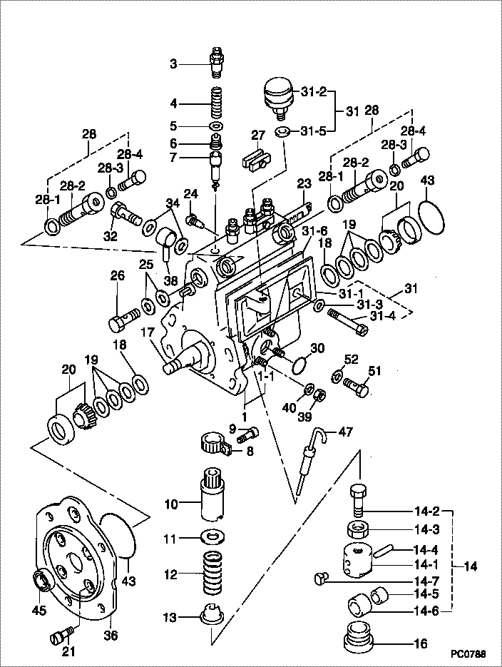
| 000. | [01] | 09010-01641 | BODY ASSY, INJECTI | |
| 001. | [01] | 19011-00923 | HOUSING KIT, INJEC | MM501003 |
| 001-001. | [03] | 94904-30010 | BOLT, STUD | ME702091 |
| 003. | [04] | 09013-10010 | HOLDER, DELIVERY V | ME022081 |
| 004. | [04] | 09013-60010 | SPRING, DELIVERY V | MM500666 |
| 005. | [04] | 09013-70010 | GASKET, DELIVERY V | ME022084 |
| 006. | [04] | 09014-00010 | VALVE SUB-ASSY, IN | MM500669 |
| 007. | [04] | 09015-01061 | ELEMENT SUB-ASSY, | |
| 008. | [04] | 09015-60010 | PINION, PLUNGER CO | ME702058 |
| 009. | [04] | 09015-70010 | SCREW, PLUNGER CON | ME702059 |
| 010. | [04] | 09016-10330 | SLEEVE, PLUNGER CO | ME702060 |
| 011. | [04] | 09016-30010 | SEAT, SPRING, UPR | ME702061 |
| 011. | [04] | 09016-30191 | SEAT, SPRING, UPR | ME736080 |
| 012. | [04] | 09016-40010 | SPRING, PUMP PLUNG | ME702062 |
| 013. | [04] | 09016-50010 | SEAT, SPRING, LWR | ME702063 |
| 014. | [04] | 09017-00020 | TAPPET SUB-ASSY,IN | |
| 014. | [04] | 09017-00130 | TAPPET SUB-ASSY,IN | ME702064 |
| 014-001. | [04] | 09017-10173 | TAPPET, INJECTION | |
| 014-001. | [04] | 09016-90130 | BODY, INJECTION PU | ME702065 |
| 014-001. | [04] | 09016-90110 | BODY, INJECTION PU | |
| 014-002. | [04] | 09017-30010 | BOLT, INJECTION PU | ME702066 |
| 014-003. | [04] | 09017-40010 | NUT, INJECTION PUM | ME702067 |
| 014-004. | [04] | 09017-60010 | PIN, INJECTION PUM | ME702068 |
| 014-005. | [04] | 09017-80010 | BUSHING, INJECTION | ME022126 |
| 014-005. | [04] | 09017-80030 | BUSHING, INJECTION | ME702069 |
| 014-006. | [04] | 09018-10010 | ROLLER, INJECTION | ME022127 |
| 014-006. | [04] | 09018-10030 | ROLLER, INJECTION | ME702070 |
| 014-007. | [04] | 09017-50040 | SLIDER | ME736247 |
| 016. | [04] | 09018-90090 | PLUG, INJECTION PU | ME703276 |
| 017. | [01] | 09019-10082 | CAMSHAFT, INJECTIO | MM500682 |
| 018. | [02] | 09019-30020 | RING, CAMSHAFT ADJ | ME702074 |
| 019. | [6C] | 09019-40290 | PLATE, CAMSHAFT SH | ME703274 |
| 019. | [6C] | 09019-40150 | PLATE, CAMSHAFT SH | ME703273 |
| 019. | [6C] | 09019-40140 | PLATE, CAMSHAFT SH | ME703272 |
| 019. | [6C] | 09019-40110 | PLATE, CAMSHAFT SH | ME703583 |
| 019. | [6C] | 09019-40060 | PLATE, CAMSHAFT SH | ME022103 |
| 019. | [6C] | 09019-40050 | PLATE, CAMSHAFT SH | ME022102 |
| 019. | [6C] | 09019-40040 | PLATE, CAMSHAFT SH | ME022101 |
| 019. | [6C] | 09019-40030 | PLATE, CAMSHAFT SH | ME022100 |
| 019. | [6C] | 09019-40020 | PLATE, CAMSHAFT SH | ME022099 |
| 019. | [6C] | 09019-40010 | PLATE, CAMSHAFT SH | ME702075 |
| 020. | [02] | 94910-10120 | BEARING, ROLLER | ME702096 |
| 021. | [04] | 94900-72471 | SCREW, W/WASHER | |
| 023. | [01] | 09021-20020 | RACK, CONTROL | MM500699 |
| 024. | [01] | 09021-50060 | SCREW, RACK GUIDE | ME728163 |
| 025. | [02] | 09022-20070 | WASHER, FUEL PIPE | ME702217 |
| 026. | [01] | 94918-00310 | SCREW, HOLLOW | ME702236 |
| 027. | [02] | 09023-00031 | PLATE SET, VALVE H | ME702082 |
| 028. | [02] | 09024-00010 | BLEEDER SUB-ASSY, | ME702083 |
| 028-001. | [02] | 09024-10010 | WASHER, AIR BLEEDE | ME702102 |
| 028-002. | [02] | 09024-20010 | NIPPLE, AIR BLEEDE | ME022094 |
| 028-003. | [02] | 09024-30030 | PACKING, AIR BLEED | ME702057 |
| 028-004. | [02] | 09024-40010 | SCREW, AIR BLEEDER | MM501930 |
| 030. | [01] | 94914-00380 | O-RING | ME702097 |
| 031. | [01] | 09027-00531 | COVER SUB-ASSY, IN | |
| 031-001. | [01] | 09027-10211 | PLATE, INJECTION P | |
| 031-002. | [01] | 09028-00040 | CLEANER, INJECTION | ME022089 |
| 031-003. | [02] | 09024-30030 | PACKING, AIR BLEED | ME702057 |
| 031-004. | [02] | 09027-60030 | SCREW | ME703028 |
| 031-005. | [01] | 09024-10010 | WASHER, AIR BLEEDE | ME702102 |
| 031-006. | [01] | 09027-20210 | GASKET, INJECTION | ME703052 |
| 032. | [01] | 94918-00600 | SCREW, HOLLOW | MM501002 |
| 034. | [02] | 09025-10010 | WASHER, INJECTION | ME702595 |
| 036. | [01] | 09020-40071 | FLANGE, INJECTION | MM500696 |
| 038. | [01] | 19025-00021 | PIPE ASSY, OVERFLO | 31661-13800 |
| 039. | [03] | 90160-06051 | NUT, HEXAGON | ME702588 |
| 040. | [03] | 90258-06001 | WASHER, SPRING | ME702596 |
| 043. | [02] | 94914-00060 | O-RING | MM500727 |
| 045. | [01] | 94915-00930 | SEAL, OIL | MM500905 |
| 047. | [01] | 09106-00080 | GAUGE SUB-ASSY, GO | ME022613 |
| 051. | [01] | 09024-90010 | SCREW, DRAIN | ME022112 |
| 052. | [01] | 09024-80010 | WASHER, DRAIN SCRE | ME702175 |
Include in #3:
09000-05012
as BODY ASSY, INJECTI
09010-01641
Cross reference number
| Part num | Firm num | Firm | Name |
| 09010-01641 | BODY ASSY, INJECTI |
Information:
1. Install the turbocharger on Tool (A).2. Put alignment marks on the two housings and cartridge assembly of the turbocharger for correct alignment during assembly.3. Loosen clamp (3), and remove compressor housing (4) from cartridge assembly (2).4. Loosen the remaining clamp, and remove cartridge assembly (2) from turbine housing (1).
Typical Example5. Put the cartridge group (shown in the illustration) with nut (16) up in Tool (B). Use a 5S9566 Sliding T-Wrench and a universal socket to remove nut (16) that holds the compressor wheel (15) to the wheel assembly (19).6. Remove compressor wheel (15) and housing assembly (6) from wheel assembly (19). Remove piston ring (13) from the wheel assembly.7. Use Tool (C), and remove snap ring (5) from housing assembly (6). Remove insert (14) and sleeve (18) from the housing assembly. Remove seal (22) from insert (14). Remove ring (20) from sleeve (18).8. Remove oil deflector (23), thrust ring (21), bearing assembly (7), spacer sleeve (24) and thrust ring (8) from housing assembly (6).9. Use Tool (D), and remove snap ring (9) from the housing assembly. Remove bearing (25). Remove snap ring (10) with Tool (D).10. Use Tool (D), and remove snap ring (12) from the housing assembly. Remove bearing (26). Remove snap ring (11) with Tool (D).11. Check all the parts of the turbocharger for damage. If any parts are damaged, use new parts for replacement. See Special Instruction Form No. SMHS6854 for turbocharger reconditioning. Also, see Guidelines For Reusable Parts, Form No. SEBF8018. The following steps are for assembly of the turbocharger.12. Make sure that all the oil passages in the turbocharger cartridge housing are clean and free of dirt and foreign material. Do not put oil on any parts of the turbocharger until after the compressor wheel has been installed. After the turbocharger has been assembled, put clean engine oil into the oil inlet of the turbocharger.
Make sure the snap rings that hold bearings (25) and (26) in housing assembly (6) are installed with the round edge of the outside diameter toward the bearing.
13. Install snap ring (11) with Tool (D). Install bearing (26). Install snap ring (12) with Tool (D).14. Install snap ring (10) with Tool (D). Install bearing (25). Install snap ring (9) with Tool (D).15. Put wheel assembly (19) in position on Tool (B) with the threaded portion end up.