Information body assy, injecti
Rating:
Scheme ###:
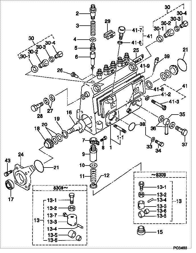
| 000. | [01] | 09010-01540 | BODY ASSY, INJECTI | 6 302 1200 20 |
| 001. | [01] | 09010-90031 | HOUSING SUB-ASSY, | 22101-1480 |
| 001-001. | [03] | 94904-30010 | BOLT, STUD | 22857-1060A |
| 002. | [06] | 09013-10020 | HOLDER, DELIVERY V | 6 053 1250 60 |
| 003. | [06] | 09013-60070 | SPRING, DELIVERY V | 6 056 1200 30 |
| 004. | [06] | 09013-70010 | GASKET, DELIVERY V | 22847-1450 |
| 005. | [06] | 09014-00010 | VALVE SUB-ASSY, IN | 2210E-77020 |
| 006. | [06] | 09015-01000 | ELEMENT SUB-ASSY, | 22104-1540 |
| 007. | [06] | 09015-60010 | PINION, PLUNGER CO | 22128-1020A |
| 008. | [06] | 09015-70010 | SCREW, PLUNGER CON | 22865-1280A |
| 009. | [06] | 09016-10330 | SLEEVE, PLUNGER CO | 22118-1310A |
| 010. | [06] | 09016-30191 | SEAT, SPRING, UPR | 22119-1190A |
| 011. | [06] | 09016-40010 | SPRING, PUMP PLUNG | 6 056 1200 80 |
| 012. | [06] | 09016-50010 | SEAT, SPRING, LWR | 22122-1060 |
| 013. | [06] | 09017-00020 | TAPPET SUB-ASSY,IN | 2210G-77020 |
| 013. | [06] | 09017-00130 | TAPPET SUB-ASSY,IN | 22105-1260 |
| 013-001. | [06] | 09017-30010 | BOLT, INJECTION PU | 0901H-30010 |
| 013-002. | [06] | 09017-40010 | NUT, INJECTION PUM | 6 053 1252 40 |
| 013-003. | [06] | 09016-90110 | BODY, INJECTION PU | 6 306 1205 20 |
| 013-003. | [06] | 09016-90130 | BODY, INJECTION PU | 22145-1010 |
| 013-003. | [06] | 09017-10173 | TAPPET, INJECTION | |
| 013-004. | [06] | 09017-60010 | PIN, INJECTION PUM | 22105-1130 |
| 013-005. | [06] | 09018-10010 | ROLLER, INJECTION | 22105-1140 |
| 013-005. | [06] | 09018-10030 | ROLLER, INJECTION | |
| 013-006. | [06] | 09017-80010 | BUSHING, INJECTION | 22105-1150 |
| 013-006. | [06] | 09017-80030 | BUSHING, INJECTION | |
| 013-007. | [06] | 09017-50040 | SLIDER | 6 306 1205 40 |
| 015. | [06] | 09018-90090 | PLUG, INJECTION PU | 22845-1420A |
| 016. | [01] | 09019-10021 | CAMSHAFT, INJECTIO | 22123-1210 |
| 017. | [01] | 94915-01750 | SEAL, OIL | 22823-1220 |
| 018. | [02] | 94910-10120 | BEARING, ROLLER | 22837-1230A |
| 019. | [02] | 09019-30020 | RING, CAMSHAFT ADJ | 22124-1160A |
| 020. | [6C] | 09019-40060 | PLATE, CAMSHAFT SH | 22885-4950A |
| 020. | [6C] | 09019-40050 | PLATE, CAMSHAFT SH | 22885-4940A |
| 020. | [6C] | 09019-40040 | PLATE, CAMSHAFT SH | 22885-4930A |
| 020. | [6C] | 09019-40030 | PLATE, CAMSHAFT SH | 22885-4920A |
| 020. | [6C] | 09019-40020 | PLATE, CAMSHAFT SH | 22885-4910A |
| 020. | [6C] | 09019-40010 | PLATE, CAMSHAFT SH | 22885-4900A |
| 021. | [02] | 94914-00060 | O-RING | 22813-1280 |
| 024. | [01] | 09020-10053 | COVER, BEARING | 6 053 1257 10 |
| 025. | [01] | 09021-00111 | RACK ASSY, CONTROL | 22113-1170 |
| 026. | [01] | 09021-50060 | SCREW, RACK GUIDE | 22811-4850A |
| 027. | [02] | 09022-20070 | WASHER, FUEL PIPE | 0 902 2200 70 |
| 027. | [02] | 09022-20011 | WASHER, FUEL PIPE | 22873-1240 |
| 028. | [01] | 94918-00310 | SCREW, HOLLOW | 22835-1310A |
| 029. | [03] | 09023-00031 | PLATE SET, VALVE H | 22109-1090A |
| 030. | [02] | 09024-00010 | BLEEDER SUB-ASSY, | 22106-1060 |
| 030-001. | [02] | 09024-10010 | WASHER, AIR BLEEDE | 22847-2150A |
| 030-002. | [02] | 09024-20010 | NIPPLE, AIR BLEEDE | 22873-1250 |
| 030-003. | [02] | 09024-30030 | PACKING, AIR BLEED | 22847-1890A |
| 030-004. | [02] | 09024-40010 | SCREW, AIR BLEEDER | 2211H-77020 |
| 033. | [01] | 09024-80010 | WASHER, DRAIN SCRE | 22847-1730A |
| 034. | [01] | 09024-90010 | SCREW, DRAIN | 6 053 1266 20 |
| 035. | [01] | 09025-00020 | NIPPLE SUB-ASSY, O | 6 056 1325 60 |
| 036. | [02] | 09025-10010 | WASHER, INJECTION | 22865-1290A |
| 037. | [01] | 94918-00060 | SCREW, HOLLOW | 22835-1110A |
| 037. | [01] | 94918-00600 | SCREW, HOLLOW | 22835-1100 |
| 038. | [01] | 94914-00380 | O-RING | 22817-1540A |
| 039. | [01] | 09029-00330 | GAUGE SUB-ASSY, IN | 22112-1110 |
| 041. | [01] | 09027-00840 | COVER SUB-ASSY, IN | 22102-1130 |
| 041-002. | [02] | 09024-30030 | PACKING, AIR BLEED | 22847-1890A |
| 041-003. | [02] | 09027-60030 | SCREW | 22815-1550A |
| 041-006. | [01] | 09024-10010 | WASHER, AIR BLEEDE | 22847-2150A |
| 041-007. | [01] | 09028-00040 | CLEANER, INJECTION | 0 902 8000 40 |
| 041-008. | [01] | 09027-10201 | PLATE, INJECTION P | |
| 041-009. | [01] | 09027-20220 | GASKET, INJECTION | 22847-2180A |
| 043. | [04] | 94904-71360 | BOLT, W/WASHER | 22815-2500A |
Include in #3:
09000-04430
as BODY ASSY, INJECTI
09010-01540
Cross reference number
| Part num | Firm num | Firm | Name |
| 09010-01540 | 6 302 1200 | BODY ASSY, INJECTI | |
| 6 302 1200 20 | HINO | BODY ASSY, INJECTI |
Information:
(1) 7S7144 Spring for valves (new): Length under test force ... 44.86 mm (1.766 in.)Test force ... 257 25 N (57.7 4.5 lb.)Use again minimum load at length under test force ... 217 N (48.83 lb.)Length of spring at valve open position ... 32.28 mm (1.271 in.)Use again minimum load at valve open position ... 658 N (148.5 lb.)Free length after test ... 52.07 mm (2.05 in.)Outside diameter ... 35.21 mm (1.386 in.)Spring must not be bent more than ... 1.82 mm (.072 in.)(2) Height to top of valve guide ... 22.23 0.25 mm (.875 .010 in.)(3) Diameter of valve stem (new) ... 9.441 0.008 mm (.3717 .0003 in.) Use again minimum diameter ... 9.408 mm (.3704 in.)Bore in valve guide with guide installed in the head.Minimum permissible (new) ... 9.456 mm (.3723 in.)Maximum permissible (worn) ... 9.581 mm (.3772 in.)(4) Valve lip thickness: 6N9916 Exhaust ValveUse again minimum ... 2.69 mm (.106 in.)6N9915 Intake ValveUse again minimum ... 2.44 mm (.096 in.)(5) Diameter of valve head: Exhaust valve ... 48.16 0.13 mm (1.896 .005 in.)Intake valve ... 51.31 0.13 mm (2.020 .005 in.)(6) Angle of valve face ... 29 1/4 1/4° (7) Depth of bore in head for valve seat insert ... 12.28 0.13 mm (.483 .005 in.)(8) Diameter of valve seat insert for exhaust valve ... 50.889 0.013 mm (2.0035 .0005 in.) Bore in head for valve seat insert for exhaust valve ... 50.813 0.030 mm (2.0005 .0012 in.)Diameter of valve seat insert for intake valve ... 52.032 0.013 mm (2.0485 .0005 in.)Bore in head for valve seat insert for intake valve ... 51.956 0.030 mm (2.0455 .0012 in.)(9) Angle of face of valve seat insert ... 30 1°(10) Maximum permissible width of valve seat (intake and exhaust) ... 1.93 mm (.076 in.) Minimum permissible width of valve seat (intake and exhaust) ... 1.14 mm (.045 in.)(11) Dimension from top of closed valve to face of head: Minimum permissible dimension for 6N9916 Exhaust Valve ... 0.66 mm (.026 in.)Minimum permissible dimension for 6N9915 Intake Valve ... 0.15 mm (.006 in.)(12) Outside diameter of the face of the valve seat insert: Exhaust seat ... 46.02 mm (1.812 in.)Maximum permissible, exhaust seat ... 47.29 mm (1.862 in.)Intake seat ... 49.28 mm (1.940 in.)Maximum permissible, intake seat ... 50.55 mm (1.990 in.)(13) Angle to grind seat face of the insert to get a reduction of maximum seat diameter ... 15°Procedure to Check Intake Valve Timing
1. Check the No. 1 intake valve clearance with the engine stopped. The valve clearance must be 0.30 to 0.46 mm (.012 to .018 in.). If the valve clearance is not in this range, adjust the clearance to .038 mm (.015 in.).2. Mark Top Center Position of the crankshaft on the vibration damper or pulley.3. Use a dial indicator to measure the intake valve movement.4. Rotate the crankshaft in the direction of normal
1. Check the No. 1 intake valve clearance with the engine stopped. The valve clearance must be 0.30 to 0.46 mm (.012 to .018 in.). If the valve clearance is not in this range, adjust the clearance to .038 mm (.015 in.).2. Mark Top Center Position of the crankshaft on the vibration damper or pulley.3. Use a dial indicator to measure the intake valve movement.4. Rotate the crankshaft in the direction of normal