Information body assy, injecti
Rating:
Scheme ###:
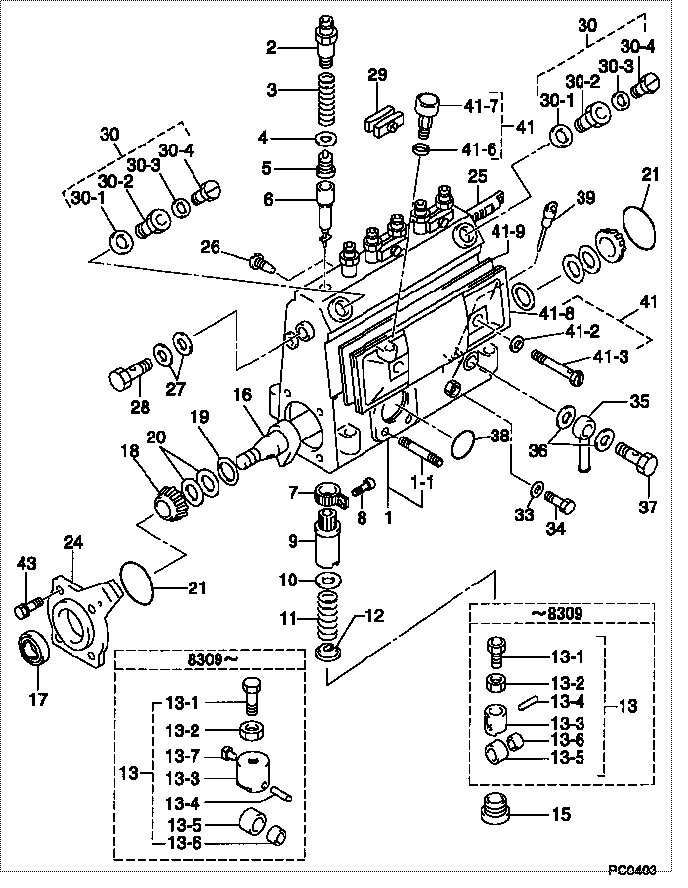
| 000. | [01] | 09010-01361 | BODY ASSY, INJECTI | 6 075 1200 20 |
| 001. | [01] | 09010-90031 | HOUSING SUB-ASSY, | 22101-1480 |
| 001. | [01] | 19011-01790 | HOUSING KIT, INJEC | |
| 001-001. | [03] | 94904-30010 | BOLT, STUD | 22857-1060A |
| 002. | [06] | 09013-10020 | HOLDER, DELIVERY V | 6 053 1250 60 |
| 003. | [06] | 09013-60070 | SPRING, DELIVERY V | 6 056 1200 30 |
| 004. | [06] | 09013-70010 | GASKET, DELIVERY V | 22847-1450 |
| 005. | [06] | 09014-00010 | VALVE SUB-ASSY, IN | 2210E-77020 |
| 006. | [06] | 09015-00800 | ELEMENT SUB-ASSY, | 22104-1530 |
| 007. | [06] | 09015-60010 | PINION, PLUNGER CO | 22128-1020A |
| 008. | [06] | 09015-70010 | SCREW, PLUNGER CON | 22865-1280A |
| 009. | [06] | 09016-10330 | SLEEVE, PLUNGER CO | 22118-1310A |
| 010. | [06] | 09016-30191 | SEAT, SPRING, UPR | 22119-1190A |
| 011. | [06] | 09016-40010 | SPRING, PUMP PLUNG | 6 056 1200 80 |
| 012. | [06] | 09016-50010 | SEAT, SPRING, LWR | 22122-1060 |
| 013. | [06] | 09017-00020 | TAPPET SUB-ASSY,IN | 2210G-77020 |
| 013. | [06] | 09017-00130 | TAPPET SUB-ASSY,IN | 22105-1260 |
| 013-001. | [06] | 09017-30010 | BOLT, INJECTION PU | 0901H-30010 |
| 013-002. | [06] | 09017-40010 | NUT, INJECTION PUM | 6 053 1252 40 |
| 013-003. | [06] | 09016-90110 | BODY, INJECTION PU | 6 306 1205 20 |
| 013-003. | [06] | 09016-90130 | BODY, INJECTION PU | 22145-1010 |
| 013-003. | [06] | 09017-10173 | TAPPET, INJECTION | |
| 013-004. | [06] | 09017-60010 | PIN, INJECTION PUM | 22105-1130 |
| 013-005. | [06] | 09018-10010 | ROLLER, INJECTION | 22105-1140 |
| 013-005. | [06] | 09018-10030 | ROLLER, INJECTION | |
| 013-006. | [06] | 09017-80010 | BUSHING, INJECTION | 22105-1150 |
| 013-006. | [06] | 09017-80030 | BUSHING, INJECTION | |
| 013-007. | [06] | 09017-50040 | SLIDER | 6 306 1205 40 |
| 015. | [06] | 09018-90090 | PLUG, INJECTION PU | 22845-1420A |
| 016. | [01] | 09019-10021 | CAMSHAFT, INJECTIO | 22123-1210 |
| 017. | [01] | 94915-01750 | SEAL, OIL | 22823-1220 |
| 018. | [02] | 94910-10120 | BEARING, ROLLER | 22837-1230A |
| 019. | [02] | 09019-30020 | RING, CAMSHAFT ADJ | 22124-1160A |
| 020. | [6C] | 09019-40060 | PLATE, CAMSHAFT SH | 22885-4950A |
| 020. | [6C] | 09019-40050 | PLATE, CAMSHAFT SH | 22885-4940A |
| 020. | [6C] | 09019-40040 | PLATE, CAMSHAFT SH | 22885-4930A |
| 020. | [6C] | 09019-40030 | PLATE, CAMSHAFT SH | 22885-4920A |
| 020. | [6C] | 09019-40020 | PLATE, CAMSHAFT SH | 22885-4910A |
| 020. | [6C] | 09019-40010 | PLATE, CAMSHAFT SH | 22885-4900A |
| 021. | [02] | 94914-00060 | O-RING | 22813-1280 |
| 024. | [01] | 09020-10090 | COVER, BEARING | 22111-1180 |
| 025. | [01] | 09021-00111 | RACK ASSY, CONTROL | 22113-1170 |
| 026. | [01] | 09021-50060 | SCREW, RACK GUIDE | 22811-4850A |
| 027. | [02] | 94901-02490 | WASHER | 22877-1100A |
| 028. | [01] | 94918-00310 | SCREW, HOLLOW | 22835-1310A |
| 029. | [03] | 09023-00031 | PLATE SET, VALVE H | 22109-1090A |
| 030. | [02] | 09024-00010 | BLEEDER SUB-ASSY, | 22106-1060 |
| 030-001. | [02] | 09024-10010 | WASHER, AIR BLEEDE | 22847-2150A |
| 030-002. | [02] | 09024-20010 | NIPPLE, AIR BLEEDE | 22873-1250 |
| 030-003. | [02] | 09024-30030 | PACKING, AIR BLEED | 22847-1890A |
| 030-004. | [02] | 09024-40010 | SCREW, AIR BLEEDER | 2211H-77020 |
| 033. | [01] | 09024-80010 | WASHER, DRAIN SCRE | 22847-1730A |
| 034. | [01] | 09024-90010 | SCREW, DRAIN | 6 053 1266 20 |
| 035. | [01] | 09025-00020 | NIPPLE SUB-ASSY, O | 6 056 1325 60 |
| 036. | [02] | 94901-02470 | WASHER | 22847-1900A |
| 037. | [01] | 94918-00060 | SCREW, HOLLOW | 22835-1110A |
| 037. | [01] | 94918-00600 | SCREW, HOLLOW | 22835-1100 |
| 038. | [01] | 94914-00380 | O-RING | 22817-1540A |
| 039. | [01] | 09029-00330 | GAUGE SUB-ASSY, IN | 22112-1110 |
| 041. | [01] | 09027-00840 | COVER SUB-ASSY, IN | 22102-1130 |
| 041-002. | [02] | 09024-30030 | PACKING, AIR BLEED | 22847-1890A |
| 041-003. | [02] | 09027-60030 | SCREW | 22815-1550A |
| 041-006. | [01] | 09024-10010 | WASHER, AIR BLEEDE | 22847-2150A |
| 041-007. | [01] | 09028-00040 | CLEANER, INJECTION | 0 902 8000 40 |
| 041-008. | [01] | 09027-10201 | PLATE, INJECTION P | |
| 041-009. | [01] | 09027-20220 | GASKET, INJECTION | 22847-2180A |
| 043. | [04] | 94904-71360 | BOLT, W/WASHER | 22815-2500A |
Include in #3:
Cross reference number
| Part num | Firm num | Firm | Name |
| 09010-01361 | 6 075 1200 | BODY ASSY, INJECTI |
Information:
Components Of The 6V4950 Injection Line Speed Pickup Group
1. 6V6114 Pickup 2. 6V6113 AmplifierModification Of 6V2100 Multitach
(1) Check your 6V2100 Multitach; if there is an "A" at the location shown, no modifications are needed to the multitach. If there is no "A", modifications must be made to the multitach. See Special Instruction Form SEHS8224 "TROUBLESHOOTING AND REPAIR OF THE 6V2100 MULTITACH", page 23, for the update modifications needed on the multitach. These modifications, if needed, must be made to the multitach to get the correct accuracy of the speed readings.Optional Items For Use With The 6V4950 Injection Line Speed Pickup Group
1. 6V2100 Multitach A programmable digital tachometer used as the speed readout for the injection line speed pickup group.2. 6V4190 Autoprogrammer An accessory for the 6V2100 Multitach which provides automatic programming whenever the multitach is powered and when switching between PH (photo) and MAG (magnetic) inputs.3. 5P7366 Power Cable Used for connecting 11 - 40 VDC power to the multitach.4. 6V2198 Extension Cable Photo input extension cable used for connecting 6V4950 Pickup Group to the 6V2100 Multitach.Specifications
Operation Instructions
IMPORTANT: To avoid personal injury and possible damage to the equipment, always observe the following warnings and cautions when using the injection line speed pickup group.
All bare metal locations on the fuel injection lines must be repainted after removal of the pickup group and before the engine is put back into service. If this is not done, the bare metal fuel injection lines can corrode. This could result in a fire if fuel is sprayed on hot engine parts.
Always install the speed pickup group in a location as far from hot engine parts (such as the exhaust manifold, turbocharger, etc.) as possible.
Keep the cables and amplifier away from hot engine parts.
Do not over-tighten the thumbscrew on the pickup; tighten by hand only. Do not use any tools to tighten the thumbscrew or damage to the pickup may result.
Do not use abrasive materials to clean the inner bore of the pickup contact or damage to the pickup may result.
(A) Installation Of The Pickup
1. Select a location for mounting the pickup on one of the engine's fuel injection lines. Although the pickup will work on any straight section of fuel injection line, the location selected should have sufficient clearance to permit installation of the pickup without touching other parts of the engine. This location on the injection line must have a minimum of 15 mm (.6") of clearance with adjacent injection lines and a minimum of 25 mm (1.0") clearance under the line as shown above. Do not attempt to install the pickup on a curved section of the injection line.2. Use a knife or emery paper to remove paint from the injection line at the pickup mounting location. Remove the paint completely from around the line in a band approximately 10 mm (.38") wide as shown above. Be careful not to nick or otherwise damage the injection line.
Repaint the fuel injection line after the pickup has been removed and the engine