Information body assy, injecti
Rating:
Scheme ###:
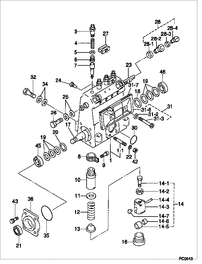
| 000. | [01] | 09010-01302 | BODY ASSY, INJECTI | 09010-01300 |
| 001. | [01] | 09010-91140 | HOUSING SUB-ASSY, | 09010-91140 |
| 001-001. | [03] | 94904-30010 | BOLT, STUD | 94904-30010 |
| 003. | [04] | 09013-10020 | HOLDER, DELIVERY V | 09013-10020 |
| 004. | [04] | 09013-60010 | SPRING, DELIVERY V | 09013-60010 |
| 005. | [04] | 09013-70010 | GASKET, DELIVERY V | 09013-70010 |
| 006. | [04] | 09014-00021 | VALVE SUB-ASSY, IN | 09014-00021 |
| 007. | [04] | 09015-00840 | ELEMENT SUB-ASSY, | 09015-00840 |
| 008. | [04] | 09015-60010 | PINION, PLUNGER CO | 09015-60010 |
| 009. | [04] | 09015-70010 | SCREW, PLUNGER CON | 09015-70010 |
| 010. | [04] | 09016-10330 | SLEEVE, PLUNGER CO | |
| 011. | [04] | 09016-30120 | SEAT, SPRING, UPR | |
| 011. | [04] | 09016-30191 | SEAT, SPRING, UPR | |
| 012. | [04] | 09016-40020 | SPRING, PUMP PLUNG | 09016-40020 |
| 013. | [04] | 09016-50010 | SEAT, SPRING, LWR | 09016-50010 |
| 014. | [04] | 09017-00020 | TAPPET SUB-ASSY,IN | 09017-00020 |
| 014. | [04] | 09017-00130 | TAPPET SUB-ASSY,IN | 09017-00130 |
| 014-001. | [04] | 09017-30010 | BOLT, INJECTION PU | 09017-30010 |
| 014-002. | [04] | 09017-40010 | NUT, INJECTION PUM | 09017-40010 |
| 014-003. | [04] | 09016-90110 | BODY, INJECTION PU | 09016-90110 |
| 014-003. | [04] | 09016-90130 | BODY, INJECTION PU | 09016-90130 |
| 014-003. | [04] | 09017-10173 | TAPPET, INJECTION | 09017-10171 |
| 014-004. | [04] | 09017-60010 | PIN, INJECTION PUM | 09017-60010 |
| 014-005. | [04] | 09018-10010 | ROLLER, INJECTION | 09018-10010 |
| 014-005. | [04] | 09018-10030 | ROLLER, INJECTION | 09018-10030 |
| 014-006. | [04] | 09017-80010 | BUSHING, INJECTION | 09017-80010 |
| 014-006. | [04] | 09017-80030 | BUSHING, INJECTION | 09017-80030 |
| 014-007. | [04] | 09017-50040 | SLIDER | |
| 016. | [04] | 09018-90090 | PLUG, INJECTION PU | |
| 017. | [01] | 09019-10082 | CAMSHAFT, INJECTIO | 09019-10081 |
| 018. | [01] | 09019-30041 | RING, CAMSHAFT ADJ | 09019-30041 |
| 019. | [6C] | 09019-40400 | PLATE, CAMSHAFT SH | |
| 019. | [6C] | 09019-40290 | PLATE, CAMSHAFT SH | |
| 019. | [6C] | 09019-40150 | PLATE, CAMSHAFT SH | 09019-40150 |
| 019. | [6C] | 09019-40140 | PLATE, CAMSHAFT SH | 09019-40140 |
| 019. | [6C] | 09019-40110 | PLATE, CAMSHAFT SH | 09019-40110 |
| 019. | [6C] | 09019-40060 | PLATE, CAMSHAFT SH | 09019-40060 |
| 019. | [6C] | 09019-40050 | PLATE, CAMSHAFT SH | 09019-40050 |
| 019. | [6C] | 09019-40040 | PLATE, CAMSHAFT SH | 09019-40040 |
| 019. | [6C] | 09019-40030 | PLATE, CAMSHAFT SH | 09019-40030 |
| 019. | [6C] | 09019-40020 | PLATE, CAMSHAFT SH | 09019-40020 |
| 019. | [6C] | 09019-40010 | PLATE, CAMSHAFT SH | 09019-40010 |
| 020. | [01] | 09019-30030 | RING, CAMSHAFT ADJ | 09019-30030 |
| 021. | [01] | 94915-01750 | SEAL, OIL | 94915-01750 |
| 022. | [03] | 90258-06001 | WASHER, SPRING | 90258-06001 |
| 023. | [01] | 09021-20020 | RACK, CONTROL | 09021-20020 |
| 024. | [01] | 09021-50060 | SCREW, RACK GUIDE | |
| 025. | [02] | 09022-20070 | WASHER, FUEL PIPE | 09022-20070 |
| 026. | [01] | 94918-00310 | SCREW, HOLLOW | 94918-00310 |
| 027. | [02] | 09023-00031 | PLATE SET, VALVE H | 09023-00031 |
| 028. | [01] | 09024-00010 | BLEEDER SUB-ASSY, | 09024-00010 |
| 028-001. | [01] | 09024-10010 | WASHER, AIR BLEEDE | 09024-10010 |
| 028-002. | [01] | 09024-20010 | NIPPLE, AIR BLEEDE | 09024-20010 |
| 028-003. | [01] | 09024-30030 | PACKING, AIR BLEED | 09024-30030 |
| 028-004. | [01] | 09024-40010 | SCREW, AIR BLEEDER | 09024-40010 |
| 030. | [01] | 94914-00380 | O-RING | 94914-00380 |
| 031. | [01] | 09027-01460 | COVER SUB-ASSY, IN | |
| 031-002. | [02] | 09024-30030 | PACKING, AIR BLEED | 09024-30030 |
| 031-003. | [02] | 09027-60030 | SCREW | 09027-60030 |
| 031-006. | [01] | 09027-50182 | PROCESSING DRAWING | |
| 031-007. | [01] | 09027-20210 | GASKET, INJECTION | 09027-20210 |
| 032. | [01] | 94918-00050 | SCREW, HOLLOW | 94918-00050 |
| 034. | [02] | 09022-20060 | WASHER, FUEL PIPE | 09022-20060 |
| 035. | [01] | 94914-00060 | O-RING | 94914-00060 |
| 036. | [01] | 09020-10081 | COVER, BEARING | 09020-10081 |
| 042. | [03] | 90160-06051 | NUT, HEXAGON | 90160-06051 |
| 043. | [04] | 94904-71360 | BOLT, W/WASHER | 94904-71360 |
| 045. | [01] | 94910-00080 | BEARING, BALL | 94910-00080 |
| 046. | [01] | 94910-00660 | BEARING, BALL | 94910-00660 |
Include in #3:
09000-03233
as BODY ASSY, INJECTI
09010-01302
Cross reference number
| Part num | Firm num | Firm | Name |
| 09010-01302 | BODY ASSY, INJECTI |
Information:
Preparation for Inspection and Adjustment of Valve Clearances
(1) Inspect and adjust valve clearances when the engine is cold.(2) Loosen the cylinder head bolts slightly, and retighten them to the specified torque in the order shown in the diagram on the right.
Cylinder head bolt tightening sequenceInspection and Adjustment of Valve Clearances
(1) Confirmation of top dead center on compression stroke for cylinder No. 1(a) By engaging the turning handle on the crankshaft pulley nut, turn the engine in the forward rotating direction (clockwise when viewed from the front of the engine). (b) Stop turning when the "0" line stamped on the periphery of the crankshaft pulley aligns with the piston on the timing gear case.(c) Move up and down the inlet and exhaust valve rocker arms of cylinder No. 1 to make sure that they are not being pushed up by the pushrods. The piston in cylinder No. 1 is at the top dead center on the compression stroke when the rocker arms are not being pushed by the pushrods (there is a clearance in each valve). If the rocker arms are being pushed up by the pushrods, turn the crankshaft one more turn.
Turning Engine
Confirmation of top dead center on compression stroke for cylinder No. 1(2) Inspection and adjustment of valve clearances(a) Insert a feeler gage between the rocker arm and valve cap to inspect the clearance. (b) Loosen the locknut, and turn the adjusting screw until the feeler gage is slightly gripped between the rocker arm and valve cap.(c) After the adjustment, tighten the lock nut securely and recheck the clearance.(d) Turn the engine, and check the valve clearances on the remaining cylinders. The inspection sequence and turning angle are as follows.
When adjusting the valve clearances after disassembly, rotate the crankshaft 2 or 3 turns after adjustment, and recheck the valve clearances to make sure that the clearances conform to the standard.
Adjustment of valve clearanceFuel System Bleeding
(1) Loosen the air vent plug of the fuel filter. (approx. 1.5 turns)(2) Move the priming pump for the filter up and down.(3) When fuel flowing from the vent hole no longer contains air bubbles, tighten the air vent plug.
Fuel system bleedingInspection and Adjustment of No-Load Minimum (Low Idling) Speed and Maximum Speed
(a) The following adjustments were inspected and set for each engine on the test bench at the factory, and the set bolts are sealed. These settings should be checked and adjusted only at our designated service shop.(b) After the governor parts are adjusted, all external stoppers must be sealed in the same way as when adjustments were made at the factory.(c) Whether the seals are intact or not has important bearing on the validity of claims under warranty. Be sure to seal all the specified sections.(d) When inspecting or adjusting, be ready to operate the engine stop lever manually in case the engine overruns (engine operation at extremely high speed).
Prior to inspection and adjustment, conduct a warm-up operation until the coolant and oil temperatures rise above 70 °C [158 °F].(1) Starting