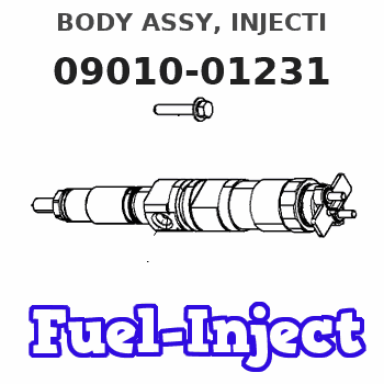
Information body assy, injecti
Rating:
Scheme ###:
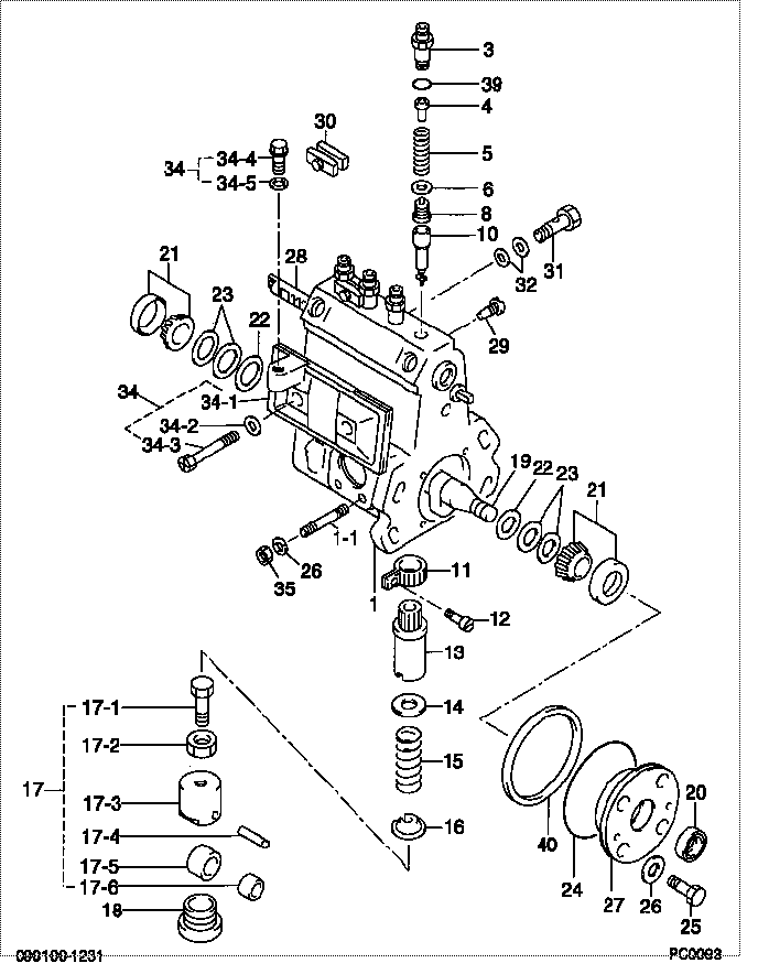
| 000. | [01] | 09010-01231 | BODY ASSY, INJECTI | 21703410 |
| 001. | [01] | 09010-90692 | HOUSING SUB-ASSY, | 0901090691 |
| 001. | [01] | 09010-91261 | HOUSING SUB-ASSY, | 0901091260 |
| 003. | [04] | 09013-10110 | HOLDER, DELIVERY V | 0901310110 |
| 003. | [04] | 09013-10250 | HOLDER, DELIVERY V | 0901310250 |
| 004. | [04] | 09013-30010 | STOPPER, DELIVERY | 21702930 |
| 005. | [04] | 09013-60120 | SPRING, DELIVERY V | 21702860 |
| 006. | [04] | 09013-70110 | GASKET, DELIVERY V | |
| 007. | [4C] | 09013-50110 | RING, ADJUSTING | |
| 007. | [4C] | 09013-50100 | RING, ADJUSTING | |
| 007. | [4C] | 09013-50090 | RING, ADJUSTING | |
| 007. | [4C] | 09013-50080 | RING, ADJUSTING | |
| 007. | [4C] | 09013-50070 | RING, ADJUSTING | 0901350070 |
| 007. | [4C] | 09013-50060 | RING, ADJUSTING | 0901350060 |
| 007. | [4C] | 09013-50050 | RING, ADJUSTING | 0901350050 |
| 007. | [4C] | 09013-50040 | RING, ADJUSTING | 0901350040 |
| 007. | [4C] | 09013-50030 | RING, ADJUSTING | 21702960 |
| 007. | [4C] | 09013-50020 | RING, ADJUSTING | 21702950 |
| 007. | [4C] | 09013-50010 | RING, ADJUSTING | 21702940 |
| 008. | [04] | 09014-00260 | VALVE SUB-ASSY, IN | 21703420 |
| 010. | [04] | 09015-00360 | ELEMENT SUB-ASSY, | 21702890 |
| 011. | [04] | 09015-60010 | PINION, PLUNGER CO | 21703220 |
| 012. | [04] | 09015-70010 | SCREW, PLUNGER CON | 21700130 |
| 013. | [04] | 09016-10160 | SLEEVE, PLUNGER CO | 21704890 |
| 014. | [04] | 09016-30010 | SEAT, SPRING, UPR | 21700150 |
| 015. | [04] | 09016-40150 | SPRING, PUMP PLUNG | 21703260 |
| 016. | [04] | 09016-50010 | SEAT, SPRING, LWR | 21700170 |
| 017. | [04] | 09017-00130 | TAPPET SUB-ASSY,IN | |
| 018. | [04] | 09018-90090 | PLUG, INJECTION PU | |
| 019. | [01] | 09019-10261 | CAMSHAFT, INJECTIO | 0901910261 |
| 020. | [01] | 94915-01750 | SEAL, OIL | |
| 021. | [02] | 94910-10120 | BEARING, ROLLER | 21706580 |
| 022. | [02] | 09019-30020 | RING, CAMSHAFT ADJ | 21703120 |
| 023. | [6C] | 09019-40150 | PLATE, CAMSHAFT SH | |
| 023. | [6C] | 09019-40140 | PLATE, CAMSHAFT SH | |
| 023. | [6C] | 09019-40060 | PLATE, CAMSHAFT SH | 21703100 |
| 023. | [6C] | 09019-40050 | PLATE, CAMSHAFT SH | 21703240 |
| 023. | [6C] | 09019-40040 | PLATE, CAMSHAFT SH | 21701050 |
| 023. | [6C] | 09019-40030 | PLATE, CAMSHAFT SH | 21703090 |
| 023. | [6C] | 09019-40020 | PLATE, CAMSHAFT SH | 21703080 |
| 023. | [6C] | 09019-40010 | PLATE, CAMSHAFT SH | 21703070 |
| 024. | [01] | 94914-00060 | O-RING | 21703340 |
| 025. | [04] | 94904-71360 | BOLT, W/WASHER | 21706600 |
| 026. | [07] | 90258-06001 | WASHER, SPRING | 9025806001 |
| 027. | [01] | 09020-10240 | COVER, BEARING | 21706610 |
| 028. | [01] | 09021-20110 | RACK, CONTROL | 21703470 |
| 029. | [01] | 09021-50060 | SCREW, RACK GUIDE | |
| 030. | [02] | 09023-00050 | PLATE SET, VALVE H | |
| 031. | [01] | 94918-00600 | SCREW, HOLLOW | 21703110 |
| 032. | [02] | 09025-10010 | WASHER, INJECTION | 21703050 |
| 034. | [01] | 09027-00213 | COVER SUB-ASSY, IN | 21704780 |
| 034-001. | [01] | 09027-50182 | PROCESSING DRAWING | |
| 034-002. | [02] | 09024-30030 | PACKING, AIR BLEED | 21703310 |
| 034-003. | [02] | 09027-60030 | SCREW | |
| 034-004. | [01] | 09027-80010 | PLUG, OIL | 21701320 |
| 034-005. | [01] | 09024-10010 | WASHER, AIR BLEEDE | 21703820 |
| 034-006. | [01] | 09027-20210 | GASKET, INJECTION | |
| 035. | [03] | 90160-06051 | NUT, HEXAGON | |
| 039. | [04] | 94914-01140 | O-RING | 21702980 |
| 039. | [04] | 90801-10180 | O-RING | 21705250 |
| 040. | [01] | 09020-60160 | GASKET, BEARING CO |
Include in #3:
Cross reference number
| Part num | Firm num | Firm | Name |
| 09010-01231 | 21703410 | BODY ASSY, INJECTI |
Information:
Disassembly and Inspection of Oil Pump
Measurement of Clearance Between Outer Rotor and Inner Rotor
Measure the clearance between the outer rotor and inner rotor, and, if the limit value is exceeded, replace the pump assembly.
Measurement of clearance between outer rotor and inner rotorMeasurement of Rotor and Case End Play
Measure the rotor and case end play, and, if the limit value is exceeded, replace the pump assembly.
Measurement of rotor and cover end playMeasurement of Clearance Between Outer Rotor and Pump Case
Measure the clearance between the outer rotor and pump case, and, if the limit value is exceeded, replace the pump assembly.
Measure the clearance between the outer rotor and caseReassembly of Oil Pump
Install the outer rotor to the pump case, check alignment mark (indentations) on the pump case cover, and then tighten the bolts. If the alignment marks are not aligned during the reassembly, the pump will not suck oil.
Alignment marks on pump case and pump case coverOil Cooler and Relief Valve
Inspection of Oil Cooler and Relief Valve
Adjustment of Relief Valve
(1) Check the relief valve and valve seat for contact condition, and the spring for fatigue and damage, and replace any defective parts.(2) Measure the valve opening pressure (oil pressure when the engine is running at rated rpm) of the relief valve, and, if the standard valve is exceeded, remove the cap bolt and make an adjustment by increasing or decreasing the shim thickness.Engine oil pressure take-out port next to oil filter
Relief Valve