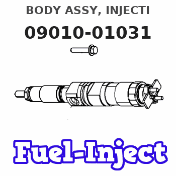
Information body assy, injecti
Rating:
Scheme ###:
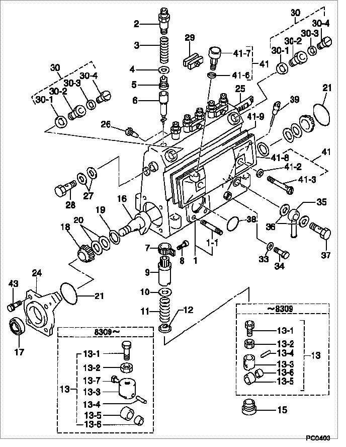
| 000. | [01] | 09010-01031 | BODY ASSY, INJECTI | 6 065 1210 00 |
| 001. | [01] | 09010-90031 | HOUSING SUB-ASSY, | 22101-1480 |
| 001. | [01] | 19011-01790 | HOUSING KIT, INJEC | |
| 001-001. | [03] | 94904-30010 | BOLT, STUD | 22857-1060A |
| 002. | [06] | 09013-10020 | HOLDER, DELIVERY V | 6 053 1250 60 |
| 003. | [06] | 09013-60070 | SPRING, DELIVERY V | 6 056 1200 30 |
| 004. | [06] | 09013-70010 | GASKET, DELIVERY V | 22847-1450 |
| 005. | [06] | 09014-00010 | VALVE SUB-ASSY, IN | 2210E-77020 |
| 006. | [06] | 09015-00350 | ELEMENT SUB-ASSY, | 22104-1370 |
| 007. | [06] | 09015-60010 | PINION, PLUNGER CO | 22128-1020A |
| 008. | [06] | 09015-70010 | SCREW, PLUNGER CON | 22865-1280A |
| 009. | [06] | 09016-10330 | SLEEVE, PLUNGER CO | 22118-1310A |
| 010. | [06] | 09016-30191 | SEAT, SPRING, UPR | 22119-1190A |
| 011. | [06] | 09016-40010 | SPRING, PUMP PLUNG | 6 056 1200 80 |
| 012. | [06] | 09016-50010 | SEAT, SPRING, LWR | 22122-1060 |
| 013. | [06] | 09017-00020 | TAPPET SUB-ASSY,IN | 2210G-77020 |
| 013. | [06] | 09017-00130 | TAPPET SUB-ASSY,IN | 22105-1260 |
| 013-001. | [06] | 09017-30010 | BOLT, INJECTION PU | 0901H-30010 |
| 013-002. | [06] | 09017-40010 | NUT, INJECTION PUM | 6 053 1252 40 |
| 013-003. | [06] | 09016-90110 | BODY, INJECTION PU | 6 306 1205 20 |
| 013-003. | [06] | 09016-90130 | BODY, INJECTION PU | 22145-1010 |
| 013-003. | [06] | 09017-10173 | TAPPET, INJECTION | |
| 013-004. | [06] | 09017-60010 | PIN, INJECTION PUM | 22105-1130 |
| 013-005. | [06] | 09018-10010 | ROLLER, INJECTION | 22105-1140 |
| 013-005. | [06] | 09018-10030 | ROLLER, INJECTION | |
| 013-006. | [06] | 09017-80010 | BUSHING, INJECTION | 22105-1150 |
| 013-006. | [06] | 09017-80030 | BUSHING, INJECTION | |
| 013-007. | [06] | 09017-50040 | SLIDER | 6 306 1205 40 |
| 015. | [06] | 09018-90090 | PLUG, INJECTION PU | 22845-1420A |
| 016. | [01] | 09019-10021 | CAMSHAFT, INJECTIO | 22123-1210 |
| 017. | [01] | 94915-01750 | SEAL, OIL | 22823-1220 |
| 018. | [02] | 94910-10120 | BEARING, ROLLER | 22837-1230A |
| 019. | [02] | 09019-30020 | RING, CAMSHAFT ADJ | 22124-1160A |
| 020. | [6C] | 09019-40150 | PLATE, CAMSHAFT SH | 22129-1200A |
| 020. | [6C] | 09019-40140 | PLATE, CAMSHAFT SH | 22129-1190A |
| 020. | [6C] | 09019-40060 | PLATE, CAMSHAFT SH | 22885-4950A |
| 020. | [6C] | 09019-40050 | PLATE, CAMSHAFT SH | 22885-4940A |
| 020. | [6C] | 09019-40040 | PLATE, CAMSHAFT SH | 22885-4930A |
| 020. | [6C] | 09019-40030 | PLATE, CAMSHAFT SH | 22885-4920A |
| 020. | [6C] | 09019-40020 | PLATE, CAMSHAFT SH | 22885-4910A |
| 020. | [6C] | 09019-40010 | PLATE, CAMSHAFT SH | 22885-4900A |
| 021. | [02] | 94914-00060 | O-RING | 22813-1280 |
| 024. | [01] | 09020-10090 | COVER, BEARING | 22111-1180 |
| 025. | [01] | 09021-20010 | RACK, CONTROL | 22113-1320A |
| 026. | [01] | 09021-50060 | SCREW, RACK GUIDE | 22811-4850A |
| 027. | [02] | 94901-02490 | WASHER | 22877-1100A |
| 028. | [01] | 94918-00310 | SCREW, HOLLOW | S2283-51310-A |
| 029. | [03] | 09023-00031 | PLATE SET, VALVE H | 22109-1090A |
| 030. | [02] | 09024-00010 | BLEEDER SUB-ASSY, | 22106-1060 |
| 030-001. | [02] | 09024-10010 | WASHER, AIR BLEEDE | 22847-2150A |
| 030-002. | [02] | 09024-20010 | NIPPLE, AIR BLEEDE | 22873-1250 |
| 030-003. | [02] | 09024-30030 | PACKING, AIR BLEED | 22847-1890A |
| 030-004. | [02] | 09024-40010 | SCREW, AIR BLEEDER | 2211H-77020 |
| 033. | [01] | 09024-80010 | WASHER, DRAIN SCRE | 22847-1730A |
| 034. | [01] | 09024-90010 | SCREW, DRAIN | 6 053 1266 20 |
| 035. | [01] | 09025-00020 | NIPPLE SUB-ASSY, O | 6 056 1325 60 |
| 036. | [02] | 94901-02470 | WASHER | 22847-1900A |
| 037. | [01] | 94918-00060 | SCREW, HOLLOW | 22835-1110A |
| 037. | [01] | 94918-00600 | SCREW, HOLLOW | 22835-1100 |
| 038. | [01] | 94914-00380 | O-RING | 22817-1540A |
| 039. | [01] | 09029-00330 | GAUGE SUB-ASSY, IN | 22112-1110 |
| 041. | [01] | 09027-00840 | COVER SUB-ASSY, IN | 22102-1130 |
| 041-002. | [02] | 09024-30030 | PACKING, AIR BLEED | 22847-1890A |
| 041-003. | [02] | 09027-60030 | SCREW | 22815-1550A |
| 041-006. | [01] | 09024-10010 | WASHER, AIR BLEEDE | 22847-2150A |
| 041-007. | [01] | 09028-00040 | CLEANER, INJECTION | 0 902 8000 40 |
| 041-008. | [01] | 09027-10201 | PLATE, INJECTION P | |
| 041-009. | [01] | 09027-20220 | GASKET, INJECTION | 22847-2180A |
| 043. | [04] | 94904-71360 | BOLT, W/WASHER | 22815-2500A |
Include in #3:
09000-02204
as BODY ASSY, INJECTI
09010-01031
Cross reference number
| Part num | Firm num | Firm | Name |
| 09010-01031 | 6 065 1210 | BODY ASSY, INJECTI |
Information:
E1To Remove the Cylinder Head
1. Drain the cooling system.2. Disconnect battery terminals.3. Detach the exhaust pipe. Remove turbocharger (T4.236 only).4. Remove the atomiser leak-off pipe assembly.5. Remove the fuel pipes from the fuel injection pump outlet and inlet to filter.6. Disconnect fuel pipe from fuel lift pump outlet to fuel filter. Remove fuel filter.7. Remove breather assembly.
E28. Remove high pressure fuel pipes and atomisers (Fig. E.2).9. Disconnect fuel pipe and electrical lead at the thermostart.10. Remove air filter and/or connecting hose. Remove induction and exhaust manifolds.11. Detach cylinder head cover.
E4 1. Rocker Shaft Bracket2. Rocker Lever3. Oil Feed Connection12. Remove rocker assembly from cylinder head (Fig. E.4). Remove push rods.
E1213. Remove cylinder head nuts/setscrews in reverse order of tightening sequence shown in Fig. E.12.14. Remove cylinder head.To Remove the Valves
E6 Mark all valves with a corresponding mark on the cylinder head to ensure that valves are refitted to their original positions unless replaced with new ones. Earlier engines had their valves and heads numbered during assembly as illustrated in Fig. E.6.
E51. Compress spring caps and springs with a suitable valve spring compressor (Fig. E.5) and remove the two half conical collets from each valve.2. Remove spring caps, springs and valve stem oil seals. Remove valves.Cleaning
1. Remove all traces of carbon from cylinder head.2. If the water jacket of the cylinder head shows signs of excessive scale, a proprietary brand of descaling solution should be used.3. Blank off rocker oil feed oil-way between numbers 2 and 3 cylinders and remove carbon from pistons and cylinder block face.4. After valve seat machining and valve grinding operations have been carried out, all parts should be thoroughly washed.Valve Guides (Early Engines)
Engines are fitted with either detachable valve guides or the valve bores are machined direct into the cylinder head.When wear takes place in the valve bores of cylinder heads without detachable valve guides, valves with oversize stems should be fitted.Three service valves are available for both inlet and exhaust with oversize stems of 0.003 in, 0.015 in and 0.030 in (0,08, 0,38 and 0,76 mm) respectively.To fit 0.015 and 0.030 in oversize valves, the bores in the cylinder head must be reamed with a piloted reamer. Suitable reamers for carrying out this operation can be obtained from Messrs. V. L. Churchill and Co. Ltd. (see Appendix).Where detachable valve guides are fitted, these can be replaced.To fit new guides; clean the parent bore, smear the outer surface of the guide with clean oil and press home the guide until 0.625 in (15,87 mm) is protruding above the cylinder head. The guides are manufactured from cast iron and are brittle.Valves and Valve Seats
Check the valve stems for wear and their fit in the guides.Examine the valve faces for pitting or distortion. Valve refacing should be at an angle of 45° or 30° for inlet valves on T4.236 engines (see Page B.10). Valves should always be refitted to their original seats and any new valve fitted should be suitably marked to identify its position if