Information body assy, injecti

Rating:
Scheme ###:
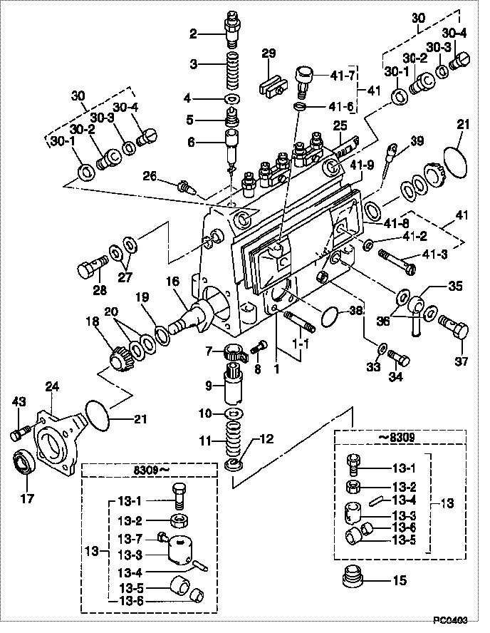
| 000. | [01] | 09010-01021 | BODY ASSY, INJECTI | 6 065 1203 01 |
| 001. | [01] | 09010-90031 | HOUSING SUB-ASSY, | 22101-1480 |
| 001. | [01] | 19011-01790 | HOUSING KIT, INJEC | |
| 001-001. | [03] | 94904-30010 | BOLT, STUD | 22857-1060A |
| 002. | [06] | 09013-10020 | HOLDER, DELIVERY V | 6 053 1250 60 |
| 003. | [06] | 09013-60070 | SPRING, DELIVERY V | 6 056 1200 30 |
| 004. | [06] | 09013-70010 | GASKET, DELIVERY V | 22847-1450 |
| 005. | [06] | 09014-00010 | VALVE SUB-ASSY, IN | 2210E-77020 |
| 006. | [06] | 09015-00350 | ELEMENT SUB-ASSY, | 22104-1370 |
| 007. | [06] | 09015-60010 | PINION, PLUNGER CO | 22128-1020A |
| 008. | [06] | 09015-70010 | SCREW, PLUNGER CON | 22865-1280A |
| 009. | [06] | 09016-10330 | SLEEVE, PLUNGER CO | 22118-1310A |
| 010. | [06] | 09016-30191 | SEAT, SPRING, UPR | 22119-1190A |
| 011. | [06] | 09016-40010 | SPRING, PUMP PLUNG | 6 056 1200 80 |
| 012. | [06] | 09016-50010 | SEAT, SPRING, LWR | 22122-1060 |
| 013. | [06] | 09017-00020 | TAPPET SUB-ASSY,IN | 2210G-77020 |
| 013. | [06] | 09017-00130 | TAPPET SUB-ASSY,IN | 22105-1260 |
| 013-001. | [06] | 09017-30010 | BOLT, INJECTION PU | 0901H-30010 |
| 013-002. | [06] | 09017-40010 | NUT, INJECTION PUM | 6 053 1252 40 |
| 013-003. | [06] | 09016-90110 | BODY, INJECTION PU | 6 306 1205 20 |
| 013-003. | [06] | 09016-90130 | BODY, INJECTION PU | 22145-1010 |
| 013-003. | [06] | 09017-10173 | TAPPET, INJECTION | |
| 013-004. | [06] | 09017-60010 | PIN, INJECTION PUM | 22105-1130 |
| 013-005. | [06] | 09018-10010 | ROLLER, INJECTION | 22105-1140 |
| 013-005. | [06] | 09018-10030 | ROLLER, INJECTION | |
| 013-006. | [06] | 09017-80010 | BUSHING, INJECTION | 22105-1150 |
| 013-006. | [06] | 09017-80030 | BUSHING, INJECTION | |
| 013-007. | [06] | 09017-50040 | SLIDER | 6 306 1205 40 |
| 015. | [06] | 09018-90090 | PLUG, INJECTION PU | 22845-1420A |
| 016. | [01] | 09019-10021 | CAMSHAFT, INJECTIO | 22123-1210 |
| 017. | [01] | 94915-01750 | SEAL, OIL | 22823-1220 |
| 018. | [02] | 94910-10120 | BEARING, ROLLER | 22837-1230A |
| 019. | [02] | 09019-30020 | RING, CAMSHAFT ADJ | 22124-1160A |
| 020. | [6C] | 09019-40150 | PLATE, CAMSHAFT SH | 22129-1200A |
| 020. | [6C] | 09019-40140 | PLATE, CAMSHAFT SH | 22129-1190A |
| 020. | [6C] | 09019-40060 | PLATE, CAMSHAFT SH | 22885-4950A |
| 020. | [6C] | 09019-40050 | PLATE, CAMSHAFT SH | 22885-4940A |
| 020. | [6C] | 09019-40040 | PLATE, CAMSHAFT SH | 22885-4930A |
| 020. | [6C] | 09019-40030 | PLATE, CAMSHAFT SH | 22885-4920A |
| 020. | [6C] | 09019-40020 | PLATE, CAMSHAFT SH | 22885-4910A |
| 020. | [6C] | 09019-40010 | PLATE, CAMSHAFT SH | 22885-4900A |
| 021. | [02] | 94914-00060 | O-RING | 22813-1280 |
| 024. | [01] | 09020-10090 | COVER, BEARING | 22111-1180 |
| 025. | [01] | 09021-20010 | RACK, CONTROL | 22113-1320A |
| 026. | [01] | 09021-50060 | SCREW, RACK GUIDE | 22811-4850A |
| 027. | [02] | 94901-02490 | WASHER | 22877-1100A |
| 028. | [01] | 94918-00310 | SCREW, HOLLOW | 22835-1310A |
| 029. | [03] | 09023-00031 | PLATE SET, VALVE H | 22109-1090A |
| 030. | [02] | 09024-00010 | BLEEDER SUB-ASSY, | 22106-1060 |
| 030-001. | [02] | 09024-10010 | WASHER, AIR BLEEDE | 22847-2150A |
| 030-002. | [02] | 09024-20010 | NIPPLE, AIR BLEEDE | 22873-1250 |
| 030-003. | [02] | 09024-30030 | PACKING, AIR BLEED | 22847-1890A |
| 030-004. | [02] | 09024-40010 | SCREW, AIR BLEEDER | 2211H-77020 |
| 033. | [01] | 09024-80010 | WASHER, DRAIN SCRE | 22847-1730A |
| 034. | [01] | 09024-90010 | SCREW, DRAIN | 6 053 1266 20 |
| 035. | [01] | 09025-00020 | NIPPLE SUB-ASSY, O | 6 056 1325 60 |
| 036. | [02] | 94901-02470 | WASHER | 22847-1900A |
| 037. | [01] | 94918-00060 | SCREW, HOLLOW | 22835-1110A |
| 037. | [01] | 94918-00600 | SCREW, HOLLOW | 22835-1100 |
| 038. | [01] | 94914-00380 | O-RING | 22817-1540A |
| 039. | [01] | 09029-00330 | GAUGE SUB-ASSY, IN | 22112-1110 |
| 041. | [01] | 09027-00840 | COVER SUB-ASSY, IN | 22102-1130 |
| 041-002. | [02] | 09024-30030 | PACKING, AIR BLEED | 22847-1890A |
| 041-003. | [02] | 09027-60030 | SCREW | 22815-1550A |
| 041-006. | [01] | 09024-10010 | WASHER, AIR BLEEDE | 22847-2150A |
| 041-007. | [01] | 09028-00040 | CLEANER, INJECTION | 0 902 8000 40 |
| 041-008. | [01] | 09027-10201 | PLATE, INJECTION P | |
| 041-009. | [01] | 09027-20220 | GASKET, INJECTION | 22847-2180A |
| 043. | [04] | 94904-71360 | BOLT, W/WASHER | 22815-2500A |
Include in #3:
09010-01021
as BODY ASSY, INJECTI
Cross reference number
| Part num | Firm num | Firm | Name |
| 09010-01021 | 6 065 1203 | BODY ASSY, INJECTI |
Information:
1. Remove plug (1) from the fuel injection pump housing.2. Use Tool (D) to loosen nut (2) for the fuel injection pump to be removed. Disconnect the fuel injection line nuts, and remove the felt washer. 3. Install Tool (A) in the fuel pump housing as shown with the square end down. Use a small amount of hand force to push down on Tool (A) while the control lever is moved forward to the "FUEL ON" position. Rack travel will stop in the center (zero) position. Hold a light forward force on the governor control lever to keep the fuel racks in the center (zero) position.4. Use Tool (B) to remove bushing (3) from the fuel injection pump housing. 5. Remove bushing (3) and O-ring seal (4).
When injection pumps, spacers and lifters are removed from the injection pump housing, keep the parts of each pump together so they can be installed in their original location.
6. Use Tool (C) to remove fuel injection pump (5). 7. Remove spacer (6) from the fuel injection pump housing. Make a note of the position from which each spacer was removed so each spacer can be installed in its original position.
Be careful when the fuel injection pumps are disassembled. Do not damage the surfaces of the plungers, barrels and bonnets. Any scratches will cause leakage inside the fuel injection pump. The plunger and barrel for each pump are made as a set. Do not put the plunger of one pump in the barrel of another pump. The check assemblies are made as a set. Do not mix the parts of the different check assemblies. Do not remove or make any adjustments of the gear segment on the plunger. It has been preset at the factory. If one part has wear, install a complete new pump assembly. Be careful when the plunger is put into the bore of the barrel.
8. Disassemble the fuel injection pump as follows: Remove ring (7). Separate bonnet (10) from barrel (9). Remove the spring and the check assembly from the bonnet. Remove plunger (8), the washer and spring from barrel (9).Install Fuel Injection Pumps
1. Inspect all parts for wear or damage. The plunger and barrel are serviced only as an assembly. 2. Put clean diesel fuel on plunger (1). Put plunger (1), washer (6) and spring (2) in position on barrel (3).3. Put check valve assembly (7) and spring (8) in bonnet (9). Connect bonnet (9) and barrel (3) together with ring (4). 4. Put spacer (10) into position in the pump housing bore. Be sure the correct spacer is with each pump. 5. Note the location of dowels (11) and (12) in the fuel injection pump housing. These dowels are for alignment of the fuel injection pump. 6. Slot (13) in gear segment (5) must align with dowel (11).7. Groove (14) must engage with dowel (12). 8. Use Tool (A) to put the fuel racks in the center (zero) position. See Remove Fuel Injection Pumps.9. Use Tool (E)