Information body assy, injecti
Rating:
Scheme ###:
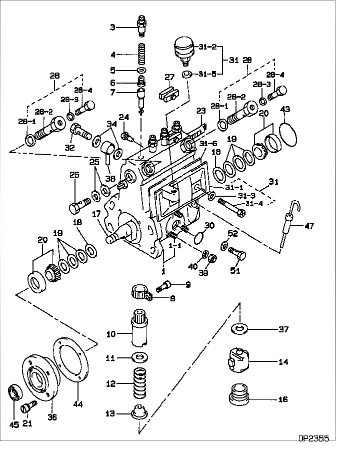
| 000. | [01] | 09010-00622 | BODY ASSY, INJECTI | 04203-20112 |
| 001. | [01] | 09010-90344 | HOUSING SUB-ASSY, | |
| 001-001. | [03] | 94904-30010 | BOLT, STUD | 85265-00057 |
| 003. | [04] | 09013-10010 | HOLDER, DELIVERY V | 09013-10010 |
| 004. | [04] | 09013-60040 | SPRING, DELIVERY V | 09013-60040 |
| 005. | [04] | 09013-70010 | GASKET, DELIVERY V | 85265-00019 |
| 006. | [04] | 09014-00061 | VALVE SUB-ASSY, IN | MM500964 |
| 007. | [04] | 09015-00350 | ELEMENT SUB-ASSY, | 09015-00350 |
| 008. | [04] | 09015-60010 | PINION, PLUNGER CO | 85265-00074 |
| 009. | [04] | 09015-70010 | SCREW, PLUNGER CON | 85265-00027 |
| 010. | [04] | 09016-10330 | SLEEVE, PLUNGER CO | |
| 011. | [04] | 09016-30191 | SEAT, SPRING, UPR | |
| 011. | [04] | 09016-30010 | SEAT, SPRING, UPR | 09016-30010 |
| 012. | [04] | 09016-40090 | SPRING, PUMP PLUNG | 09016-40090 |
| 013. | [04] | 09016-50020 | SEAT, SPRING, LWR | 09016-50020 |
| 014. | [04] | 09017-00070 | TAPPET SUB-ASSY,IN | 09017-00070 |
| 016. | [04] | 09018-90090 | PLUG, INJECTION PU | 09018-90090 |
| 017. | [01] | 09019-10082 | CAMSHAFT, INJECTIO | 09019-10081 |
| 018. | [02] | 09019-30020 | RING, CAMSHAFT ADJ | 09019-30020 |
| 019. | [6C] | 09019-40290 | PLATE, CAMSHAFT SH | |
| 019. | [6C] | 09019-40150 | PLATE, CAMSHAFT SH | |
| 019. | [6C] | 09019-40140 | PLATE, CAMSHAFT SH | |
| 019. | [6C] | 09019-40110 | PLATE, CAMSHAFT SH | 09019-40110 |
| 019. | [6C] | 09019-40060 | PLATE, CAMSHAFT SH | 09019-40060 |
| 019. | [6C] | 09019-40050 | PLATE, CAMSHAFT SH | 09019-40050 |
| 019. | [6C] | 09019-40040 | PLATE, CAMSHAFT SH | 09019-40040 |
| 019. | [6C] | 09019-40030 | PLATE, CAMSHAFT SH | 09019-40030 |
| 019. | [6C] | 09019-40020 | PLATE, CAMSHAFT SH | 09019-40020 |
| 019. | [6C] | 09019-40010 | PLATE, CAMSHAFT SH | 09019-40010 |
| 020. | [02] | 94910-10120 | BEARING, ROLLER | 94910-10121 |
| 021. | [04] | 94904-71360 | BOLT, W/WASHER | 94904-71360 |
| 023. | [01] | 09021-20020 | RACK, CONTROL | 09021-20020 |
| 024. | [01] | 09021-50060 | SCREW, RACK GUIDE | 09021-50060 |
| 025. | [02] | 09022-20070 | WASHER, FUEL PIPE | 85265-00079 |
| 026. | [01] | 94918-00310 | SCREW, HOLLOW | 85265-00078 |
| 027. | [02] | 09023-00031 | PLATE SET, VALVE H | 85265-00052 |
| 028. | [02] | 09024-00010 | BLEEDER SUB-ASSY, | 09024-00010 |
| 028-001. | [02] | 09024-10010 | WASHER, AIR BLEEDE | MM500486 |
| 028-002. | [02] | 09024-20010 | NIPPLE, AIR BLEEDE | 85265-00013 |
| 028-003. | [02] | 09024-30030 | PACKING, AIR BLEED | 85265-00016 |
| 028-004. | [02] | 09024-40010 | SCREW, AIR BLEEDER | 09024-40010 |
| 030. | [01] | 94914-00380 | O-RING | 85265-00084 |
| 031. | [01] | 09027-00322 | COVER SUB-ASSY, IN | |
| 031-001. | [01] | 09027-10211 | PLATE, INJECTION P | |
| 031-002. | [01] | 09028-00040 | CLEANER, INJECTION | 05533-01900 |
| 031-003. | [02] | 09024-30030 | PACKING, AIR BLEED | 85265-00016 |
| 031-004. | [02] | 09027-60030 | SCREW | |
| 031-005. | [01] | 09024-10010 | WASHER, AIR BLEEDE | MM500486 |
| 031-006. | [01] | 09027-20210 | GASKET, INJECTION | |
| 032. | [01] | 94918-00091 | SCREW, HOLLOW | 85265-00042 |
| 034. | [02] | 09025-10010 | WASHER, INJECTION | 85265-00077 |
| 036. | [01] | 09020-10240 | COVER, BEARING | |
| 037. | [4C] | 09031-10290 | PLATE, TAPPET ADJU | |
| 037. | [4C] | 09031-10150 | PLATE, TAPPET ADJU | 09031-10150 |
| 037. | [4C] | 09031-10140 | PLATE, TAPPET ADJU | 09031-10140 |
| 037. | [4C] | 09031-10130 | PLATE, TAPPET ADJU | 09031-10130 |
| 037. | [4C] | 09031-10120 | PLATE, TAPPET ADJU | 09031-10120 |
| 037. | [4C] | 09031-10110 | PLATE, TAPPET ADJU | 09031-10110 |
| 037. | [4C] | 09031-10100 | PLATE, TAPPET ADJU | 09031-10100 |
| 037. | [4C] | 09031-10090 | PLATE, TAPPET ADJU | 09031-10090 |
| 037. | [4C] | 09031-10080 | PLATE, TAPPET ADJU | 09031-10080 |
| 037. | [4C] | 09031-10070 | PLATE, TAPPET ADJU | 09031-10070 |
| 037. | [4C] | 09031-10060 | PLATE, TAPPET ADJU | 09031-10060 |
| 037. | [4C] | 09031-10050 | PLATE, TAPPET ADJU | 09031-10050 |
| 037. | [4C] | 09031-10040 | PLATE, TAPPET ADJU | 09031-10040 |
| 037. | [4C] | 09031-10030 | PLATE, TAPPET ADJU | 09031-10030 |
| 037. | [4C] | 09031-10020 | PLATE, TAPPET ADJU | 09031-10020 |
| 037. | [4C] | 09031-10010 | PLATE, TAPPET ADJU | 09031-10010 |
| 038. | [01] | 19025-00021 | PIPE ASSY, OVERFLO | MM500716 |
| 039. | [03] | 90160-06051 | NUT, HEXAGON | 85265-00085 |
| 040. | [03] | 90258-06001 | WASHER, SPRING | 90258-06001 |
| 043. | [01] | 94914-00060 | O-RING | 85265-00061 |
| 044. | [01] | 09020-60010 | GASKET, BEARING CO | 09020-60010 |
| 044. | [01] | 09020-60160 | GASKET, BEARING CO | |
| 045. | [01] | 94915-00570 | SEAL, OIL | 94915-00570 |
| 047. | [01] | 09106-00080 | GAUGE SUB-ASSY, GO | 09106-00080 |
| 051. | [01] | 09024-90010 | SCREW, DRAIN | 85265-00058 |
| 052. | [01] | 09024-80010 | WASHER, DRAIN SCRE | 09024-80010 |
Include in #3:
09000-00956
as BODY ASSY, INJECTI
09010-00622
Cross reference number
| Part num | Firm num | Firm | Name |
| 09010-00622 | 04203-2011 | BODY ASSY, INJECTI |
Information:
References
Safety
Before starting the procedure of mounting the fuel injection pump and tooling onto the test stand, make sure the Emergency Stop button is pushed IN. Another recommended safety precaution is to turn the power OFF and lock-out the electrical box. An SEHS7332 "Warning: Do Not Operate" tag should also be placed on the electrical box.
Illustration 1. Place Tag On Electrical Box When Working On Or Around Rotating PartsNomenclature
135-2916 Adapter Group
The parts in Charts A, B, and C are part of the 135-2916 Adapter Group and required to test 3406B, 3406C, and 3406 PEEC Engines.
Illustration 2. 135-2916 Adapter Group (front mounting hardware). Refer to Chart A for item identification.
Illustration 3. 135-2916 Adapter Group (rear mounting hardware). Refer to Chart B for item identification.
Illustration 4. 135-2916 Adapter Group (injection pump hardware). Refer to Chart C for item identification.
Illustration 5. Front and rear support clamping hardware. (Common to many mounting groups.) Drive Adapters
The drive adapters listed in Chart E are used on the original 25 mm (1.0 in) 4C-8723 Jaw Assembly or the new 4C-8192 Heavy-Duty Coupling Group. Refer to the Installation section and the charts below to determine the correct adapter. Refer to Charts F and G and Illustrations 6 and 7 for a list of drive adapters and associated hardware.
Illustration 6. Drive adapters with 25 mm (1.0 in) shaft diameters for use with 4C-8723 Jaw Assembly. Refer to Chart F for item identification.
Illustration 7. Drive adapters for use with 4C-8192 Heavy-Duty Coupling and Torque Tube. Refer to Chart G for item identification. Required Pump Testing Tooling
Illustration 8. Rack preload and positioning assembly for 3406 PEEC Engines. Refer to Chart H for item identification.
Illustration 9. Injection Pump Testing Tooling. Refer to Chart I for item identification.
Illustration 10. TMI screen. Refer to procedure below to obtain pump specifications.TMI Specifications
Delivery specifications are published "on-line" in TMI. To access these specifications, use the following procedure. For additional information on TMI, refer to NEHS0594.Finding Test Specification Data When Engine Arrangement Level, Pump Group, and Governor Group Part Numbers Are Known
The Step numbers below correspond to the item callouts in Illustration 11.1. Type "GNK401". The cursor will automatically move to the next field.2. Type in "12". Press "Enter".3. Type in the pump part number in the "ARRG/GP NUMBER" field and press "Enter". This example shows a 6I-3060 part number.4. Find the correct line number.5. Type in the line number; "011". Press "Enter".6. Scroll through the data using the "Enter" key.Installation
This procedure was written using the 4C-8192 Heavy-Duty Coupling Group, which is the preferred coupling. Refer to Charts E, F, and G for the correct adapter and associated hardware depending on which coupling group is used on the test stand.1. Push the Emergency Stop button IN.
Make sure the puller hole in the plug is facing out when the plug is installed. If the puller hole is facing in, the plug and possibly the fuel injection pump will be damaged when the plug is removed.
Illustration 11. Install Plug. Example of 8T-2849 Plug.
(A) Hole. (B) Threaded puller hole.