Information body assy, injecti
Rating:
Scheme ###:
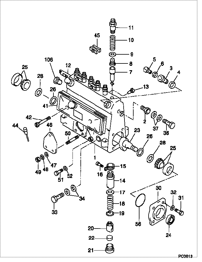
| 000. | [01] | 09010-00011 | BODY ASSY, INJECTI | 22120-76010 |
| 001. | [01] | 09011-00024 | HOUSING SUB-ASSY, | 22101-77020 |
| 002. | [01] | 09022-10010 | UNION, INJECTION P | 22127-76010 |
| 003. | [02] | 09024-20010 | NIPPLE, AIR BLEEDE | 22118-77020 |
| 004. | [02] | 09024-10010 | WASHER, AIR BLEEDE | 22119-77020 |
| 005. | [02] | 09024-40010 | SCREW, AIR BLEEDER | 22117-77020 |
| 006. | [02] | 09024-30030 | PACKING, AIR BLEED | 22121-77020 |
| 007. | [06] | 09015-00600 | ELEMENT SUB-ASSY, | 22105-77020 |
| 008. | [06] | 09014-00010 | VALVE SUB-ASSY, IN | 22104-77020 |
| 009. | [06] | 09013-70010 | GASKET, DELIVERY V | 22149-76010 |
| 010. | [06] | 09013-60010 | SPRING, DELIVERY V | 90501-13127 |
| 011. | [06] | 09013-10130 | HOLDER, DELIVERY V | |
| 012. | [01] | 09021-20010 | RACK, CONTROL | 22114-67010 |
| 013. | [01] | 09021-50060 | SCREW, RACK GUIDE | 22115-78140 |
| 014. | [06] | 09016-10160 | SLEEVE, PLUNGER CO | 22142-77020 |
| 015. | [06] | 09015-60010 | PINION, PLUNGER CO | 22155-76010 |
| 016. | [06] | 09015-70010 | SCREW, PLUNGER CON | 22156-76010 |
| 017. | [06] | 09016-30070 | SEAT, SPRING, UPR | |
| 018. | [06] | 09016-40010 | SPRING, PUMP PLUNG | 22144-67010 |
| 019. | [06] | 09016-50010 | SEAT, SPRING, LWR | 22145-67010 |
| 020. | [06] | 09017-00130 | TAPPET SUB-ASSY,IN | |
| 021. | [06] | 09018-90090 | PLUG, INJECTION PU | 22157-48024 |
| 022. | [06] | 09018-80010 | PLATE, INJECTION P | 22158-76010 |
| 023. | [01] | 09019-10710 | CAMSHAFT, INJECTIO | 22146-68010 |
| 024. | [01] | 94915-01750 | SEAL, OIL | |
| 025. | [02] | 94910-10120 | BEARING, ROLLER | 90099-10087 |
| 026. | [02] | 09019-30020 | RING, CAMSHAFT ADJ | 22147-77020 |
| 028. | [1C] | 09019-40400 | PLATE, CAMSHAFT SH | |
| 028. | [1C] | 09019-40150 | PLATE, CAMSHAFT SH | 22166-78031 |
| 028. | [1C] | 09019-40140 | PLATE, CAMSHAFT SH | 22166-78030 |
| 028. | [1C] | 09019-40060 | PLATE, CAMSHAFT SH | 22166-76010 |
| 028. | [1C] | 09019-40050 | PLATE, CAMSHAFT SH | 22165-76010 |
| 028. | [1C] | 09019-40040 | PLATE, CAMSHAFT SH | 22164-76010 |
| 028. | [1C] | 09019-40030 | PLATE, CAMSHAFT SH | 22163-76010 |
| 028. | [1C] | 09019-40020 | PLATE, CAMSHAFT SH | 22162-76010 |
| 028. | [1C] | 09019-40010 | PLATE, CAMSHAFT SH | 22161-76010 |
| 030. | [01] | 09020-10010 | COVER, BEARING | 22111-77020 |
| 031. | [04] | 94904-10130 | BOLT, SLOTTED HEXA | 90099-04037 |
| 032. | [04] | 90258-06001 | WASHER, SPRING | 94511-00600 |
| 033. | [01] | 94918-00600 | SCREW, HOLLOW | |
| 034. | [02] | 09025-10011 | WASHER, INJECTION | 22124-77020 |
| 035. | [01] | 94918-10070 | NIPPLE, SWIVELING | |
| 036. | [01] | 94918-00190 | SCREW, HOLLOW | 90099-18008 |
| 037. | [02] | 09022-20070 | WASHER, FUEL PIPE | 94712-77121 |
| 038. | [01] | 94918-10060 | NIPPLE, SWIVELING | |
| 041. | [01] | 09027-00010 | COVER SUB-ASSY, IN | 22103-77020 |
| 041. | [01] | 09027-00441 | COVER SUB-ASSY, IN | 22103-76051 |
| 041-001. | [01] | 09027-10201 | PLATE, INJECTION P | |
| 041-002. | [01] | 09027-20220 | GASKET, INJECTION | |
| 041-003. | [02] | 09027-60030 | SCREW | |
| 041-004. | [02] | 09024-30030 | PACKING, AIR BLEED | 22121-77020 |
| 041-005. | [01] | 09028-00060 | CLEANER, INJECTION | 22151-56010 |
| 041-006. | [01] | 09024-10010 | WASHER, AIR BLEEDE | 22119-77020 |
| 042. | [02] | 94900-50040 | SCREW, SLOTTED FLA | 90099-00027 |
| 044. | [01] | 09029-00010 | GAUGE SUB-ASSY, IN | 22112-77020 |
| 045. | [03] | 09023-00010 | PLATE SET, VALVE H | 22102-77020 |
| 046. | [01] | 09010-40010 | PLATE, COVER | |
| 047. | [03] | 09010-70010 | WASHER | |
| 048. | [03] | 90258-06001 | WASHER, SPRING | 94511-00600 |
| 049. | [03] | 90170-06551 | NUT, HEXAGON | 90031-70082 |
| 050. | [03] | 94904-30010 | BOLT, STUD | 90099-04071 |
| 051. | [01] | 09024-90010 | SCREW, DRAIN | 22122-77020 |
| 052. | [01] | 09024-80010 | WASHER, DRAIN SCRE | 22378-76010 |
| 056. | [02] | 94914-00060 | O-RING | 90099-14002 |
| 106. | [01] | 09052-40010 | PLUG, SCREW | 22126-76010 |
Include in #3:
Cross reference number
| Part num | Firm num | Firm | Name |
| 09010-00011 | 22120-7601 | BODY ASSY, INJECTI |
Information:
To Renew the Flywheel Ring Gear
1. Place the flywheel in a suitable container of clean cold water and support it by positioning four metal blocks under the ring gear. Arrange the flywheel assembly so that, when placed in the water the ring gear is uppermost and clear of the water line by approximately 1/4 in (6,5 mm). Heat the ring gear evenly around its circumference, thus expanding it. This will allow the flywheel to drop away from the ring gear.2. Heat the new ring gear to an approximate temperature of 475°F (246°C). Fit the gear over the flywheel with the lead-in on the teeth facing towards the front of the flywheel and allow the ring to cool.To Refit the Flywheel
1. Using the method of removal but in reverse, mount the flywheel to the crankshaft flange so that the untapped hole in the flange is in line with the seventh unused smaller hole in the flywheel.2. Engage the securing setscrews with new hardened steel washers and tighten to a torque of 80 lbf ft (11,0 kfg m) -108 Nm. Where the flywheel is secured with place bolts, without washers, these should be tightened to 90 lbf ft (12,4 kgf m) - 122 Nm. Place bolts can be identified by the 6 slots cut in the head face and the embossed letter 'T'.3. Set up a clock indicator gauge with the base secured to the flywheel housing or cylinder block and adjust the clock so that the stylus is contacting the flywheel periphery. Turn the crankshaft and check the total reading. The flywheel should run true within 0.012 in (0,30 mm) total indicator reading.
P14. Now adjust the clock gauge so that the plunger is at right angles to the crankshaft flange and rests on the vertical machined face of the flywheel, at the outermost point of the face (Fig. P.1). Press the crankshaft one way to take up the end float, and turn the flywheel. The run-out on the flywheel face should be within 0.001 in (0,025 mm) per inch (25 mm) of flywheel radius from the crankshaft axis to the clock gauge stylus. If not, remove flywheel and check mating faces for burrs and dirt.5. Lock the setscrews with the tab washers where fitted.6. Refit the clutch and gearbox, etc.To Remove the Flywheel Housing
1. Remove the flywheel.2. Unscrew the nuts or setscrews securing the flywheel housing to the cylinder block and tap the housing clear of the locating dowels.3. Examine the housing for cracks and damage etcTo Refit the Flywheel Housing
1. Fit the housing to the cylinder block.2. Refit the securing nuts or setscrews.
P23. Check concentricity (Fig. P.2.) The inner bore of of the flywheel housing must be truly central with the crankshaft within the limits listed overleaf.
P34. Check perpendicular alignment (Fig. P.3). This facing should be within the limits listed below. Diameter of Housing AllowanceUp to 141/4 in (362 mm) 0.006 in (0,15