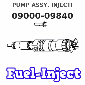
Information pump assy, injecti
Rating:
KIT List:
| Body assy, injecti | 1904400300 |
| Governor assy, mec | 1908900150 |
| Pump assy, fuel fe | 1922900060 |
Components :
| 001. | PUMP ASSY, INJECTI | 09000-09840 |
| 002. | BODY ASSY, INJECTI | 09010-02930 |
| 003. | GOVERNOR ASSY, MEC | 09080-01310 |
| 004. | PUMP ASSY, FUEL FE | 09210-00073 |
Scheme ###:
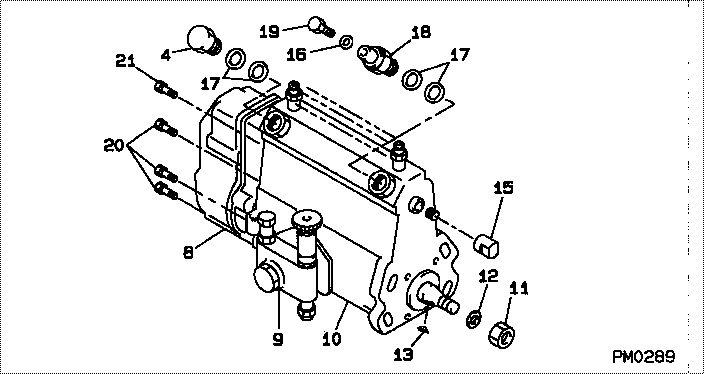
| 000. | [01] | 09000-09840 | PUMP ASSY, INJECTI | 01706821 |
| 004. | [01] | 94918-00310 | SCREW, HOLLOW | 21702980 |
| 008. | [01] | 09080-01310 | GOVERNOR ASSY, MEC | 0908001310 |
| 009. | [01] | 09210-00073 | PUMP ASSY, FUEL FE | 02001312 |
| 010. | [01] | 09010-02930 | BODY ASSY, INJECTI | |
| 011. | [01] | 94905-02450 | NUT, HEXAGON | 21703380 |
| 012. | [01] | 94901-50500 | WASHER, SPRING | 21703370 |
| 013. | [01] | 94913-00050 | KEY, WOODRUFF | |
| 015. | [01] | 09001-80140 | COVER, CONTROL RAC | 21703400 |
| 016. | [01] | 94901-81020 | WASHER, COPPER PLA | 21706370 |
| 017. | [04] | 09022-20011 | WASHER, FUEL PIPE | 21703000 |
| 017. | [04] | 09022-20070 | WASHER, FUEL PIPE | |
| 018. | [01] | 09031-00011 | VALVE ASSY, OVERFL | 21701340 |
| 019. | [01] | 09024-40080 | SCREW, AIR BLEEDER | 21704700 |
| 020. | [06] | 94900-50190 | SCREW, SLOTTED FLA | 9490050190 |
| 021. | [01] | 91518-08221 | BOLT, W/WASHER |
Include in #3:
09000-09840
as PUMP ASSY, INJECTI
Cross reference number
| Part num | Firm num | Firm | Name |
| 09000-09840 | 01706821 | PUMP ASSY, INJECTI | |
| 01706821 | MITSUI DEUTZ | PUMP ASSY, INJECTI |
Information:
DO NOT adjust the linkage so the treadle can be used to shut off the engine. If the operator is in a standing position and places a foot on the treadle, the engine could be unexpectedly shut off, creating a situation where the machine can be difficult to control.
518 Skidder
1. Move governor shaft (3) to SHUT OFF position and install lever (2) on shaft (3) at angle (A).2. Adjust length of rod (5) so stop (4) on pedal (1) is at dimension (B) from the floor plate.Angle (A) ... 35 5°Dimension (B) ... 67 1 mm (2.64 .01 in)3. Tighten nut (6) ... 12 4 N m (9 3 lb ft)D5H
1. Move governor lever (2) to high idle and install spring (6). Move governor lever (2) to vertical position and adjust stop bolt (3) to contact lever (2), back off one turn and lock.2. Position lever (9) on the splined governor shaft to 35 5° from vertical in shut off position.3. Adjust rod end (10) to obtain a free fit of bolt (8) and lever (7).4. Position lever (2) in low idle position. Use a spring scale to monitor the force needed to pull the governor lever (2), just below knob (1), from low idle to high idle position. Repeat and adjust housing (5) to obtain a force of 40 5 N (9 1 lb).5. With engine running, move governor lever (2) to high idle. At correct high idle RPM adjust high idle stop bolt (4) to contact lever (2), back off one turn and lock.6. Tighten rod end lock nuts to 14 4 N m (10 3 lb ft).
Decelerator Adjustment
(1) Decelerator pedal. (2) Decelerator rpm bolt.1. Adjust and lock decelerator rpm bolt (2) so that engine speed is: D5H (7NC, 1YD, 9HC, 2SD) ... 850 50 rpmD5H (8RC, 3MD, 1DD, 4KD) ... 1300 50 rpm with decelerator pedal (1) fully depressed.2. Recheck high idle rpm.215, 215B, 215C, 219, 225, 225B, 229
1. With control lever (3) positioned against economy idle stop, adjust cable (4) to operate engine at: 215, 215B, 215C, 219 ... 1750 50 rpm225, 225B, 229 ... 1850 50 rpm2. Tighten nuts (1) to ... 5.0 5 N m (4 .37 lb ft)3. Tighten nuts (2) to ... 100 15 N m (75 11 lb ft)936, 936E, 950B, 950E
1. Set governor shaft to the off position. Attach lever (1) approximately 35° forward from vertical.2. Assemble cable assembly (3) and rod end (2) to the governor housing.3. Adjust cable assembly (3) until hole in rod end (2) is 7 mm (.28 in) to 10 mm (.39 in) forward of the hole in the lever (1). Tighten nuts (4) to 8 5 N m (6 4 lb ft).4. Pull cable assembly (3) out to align holes and attach rod end (2) to lever (1).5. Attach governor pedal (7) to shaft.6. Set governor lever to high idle and adjust