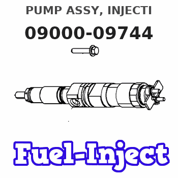
Information pump assy, injecti
Rating:
Components :
| 001. | PUMP ASSY, INJECTI | 09000-09744 |
| 002. | SWITCH KIT, CONTRO | 09009-90180 |
| 003. | BODY ASSY, INJECTI | 09010-02902 |
| 004. | COVER, BEARING | 09020-10110 |
| 005. | BODY ASSY, INJECTI | 09010-03141 |
| 006. | TIMER ASSY, AUTOMA | 09180-00961 |
| 007. | PUMP ASSY, FUEL FE | 09210-01900 |
| 008. | COUPLING ASSY | 09250-00223 |
Scheme ###:
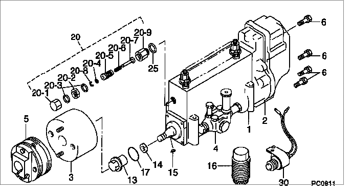
| 000. | [01] | 09000-09744 | PUMP ASSY, INJECTI | 22010-1290 |
| 001. | [01] | 09010-02902 | BODY ASSY, INJECTI | 22110-1120 |
| 001. | [01] | 09010-03141 | BODY ASSY, INJECTI | |
| 002. | [01] | 09080-04271 | GOVERNOR ASSY, MEC | |
| 003. | [01] | 09180-00962 | TIMER ASSY, AUTOMA | |
| 004. | [01] | 09210-01900 | PUMP ASSY, FUEL FE | 22570-1330A |
| 005. | [01] | 09250-00223 | COUPLING ASSY | 22610-1250 |
| 006. | [08] | 91518-06161 | BOLT, W/WASHER | 22815-1310A |
| 013. | [01] | 09001-20230 | NUT, TIMER ROUND | 22825-1110A |
| 014. | [01] | 94901-40070 | WASHER, COUNTERSUN | 22877-1190A |
| 015. | [01] | 90458-05750 | KEY, WOODRUFF | 22891-1070A |
| 016. | [01] | 09006-10011 | COVER, PRIMING PUM | 6 053 1552 60 |
| 017. | [01] | 90801-40280 | O-RING | 22817-1050A |
| 020. | [01] | 09002-00150 | CONTROL ASSY, TORO | |
| 020-001. | [01] | 09003-20090 | CAP | |
| 020-002. | [01] | 94905-30230 | NUT, HEXAGON, W/ H | |
| 020-003. | [02] | 94901-81210 | WASHER, COPPER PLA | |
| 020-004. | [1C] | 94901-31680 | WASHER, PLATE, SK | 6 056 1318 00 |
| 020-004. | [1C] | 94901-35080 | WASHER, PLATE, SK | 22885-1270A |
| 020-004. | [1C] | 94901-35090 | WASHER, PLATE, SK | 22885-1280A |
| 020-004. | [1C] | 94901-35100 | WASHER, PLATE, SK | 22885-1290A |
| 020-005. | [01] | 09002-60070 | SCREW, ADJUSTING | |
| 020-006. | [1C] | 09005-20110 | SPRING | |
| 020-006. | [1C] | 09005-20100 | SPRING | |
| 020-006. | [1C] | 09005-20070 | SPRING | |
| 020-007. | [01] | 09091-90230 | ADAPTER | |
| 020-008. | [01] | 09089-40010 | E-RING | 22863-1810A |
| 020-009. | [01] | 09001-80270 | COVER, CONTROL RAC | |
| 025. | [01] | 94901-80710 | WASHER, COPPER PLA | 22863-1300A |
| 030. | [01] | 09009-90180 | SWITCH KIT, CONTRO | 22690-1040 |
Include in #3:
09000-09744
as PUMP ASSY, INJECTI
Cross reference number
| Part num | Firm num | Firm | Name |
| 09000-09744 | 22010-1290 | PUMP ASSY, INJECTI |
Information:
Starter Motor
Disassembly
(1) Pinion set(2) Solenoid switch(3) Rear bracket(4) Brush holder(5) Brush(6) Armature(7) Yoke(8) Packing(9) Packing(10) Plate(11) Ball(12) Reduction gears(13) Lever(14) Front bracket(15) Overrunning clutch(16) Internal gear(17) Gear shaft
The pinion must be removed before removal or replacement of the following parts:1. Front bracket2. Reduction gears3. Overrunning clutch
(1) Removing Pinion
The pinion can be removed when it is held in the pushed-out position during energization of the solenoid switch. Disconnect the M-terminal connector and make a circuit that connects the starter motor and the battery as shown in the illustration. Close switches S1 and S2 to make the pinion come out and rotate. Then, open switch S2. The pinion will stop rotating but will stay in the pushed-out position. Apply a pipe-shaped implement to the pinion stopper and lightly tap it with a hammer to remove the pinion.If the pinion returns to the retracted position before disengagement of the stopper while the tool is being tapped, repeat the procedure from the beginning.
Removing pinion(2) Ball
The ball at the end of the armature acts as a bearing for movement of the armature in the thrust direction. When the armature is removed, the ball may stick to the grease on it. Be careful not to lose the ball.Inspection
(1) Armature
(a) Coil Short Circuit TestPlace the armature on a growler tester. Hold an iron rod parallel with the armature and slowly rotate the armature by hand. If the iron rod vibrates or is pulled toward the armature, the armature has a short-circuited coil and must be replaced.
Testing armature short circuit(b) Coil Ground TestCheck whether continuity exists between the commutator and shaft (or core). If continuity exists, the coil is grounded and the armature must be replaced.
Testing armature coil ground(c) Commutator Inspection(1) Measure the commutator's runout using a dial gauge. If the measurement exceeds the specified limit, rectify the problem, making sure that the outside diameter stays within specification. If the surface is rough or has stepped wear, rectify the problem with emery paper