Information pump assy, injecti
Rating:
Components :
| 001. | PUMP ASSY, INJECTI | 09000-09522 |
| 002. | BODY ASSY, INJECTI | 09010-02720 |
| 003. | COVER, BEARING | 09020-10053 |
| 004. | GOVERNOR ASSY, MEC | 09080-03690 |
| 005. | TIMER ASSY, AUTOMA | 09180-00850 |
| 006. | PUMP ASSY, FUEL FE | 09210-00930 |
| 007. | COUPLING ASSY | 09250-00211 |
Scheme ###:
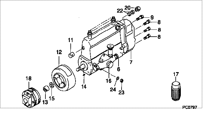
| 000. | [01] | 09000-09522 | PUMP ASSY, INJECTI | 22010-1250 |
| 006. | [01] | 09010-02720 | BODY ASSY, INJECTI | 22110-1030 |
| 007. | [01] | 09080-03690 | GOVERNOR ASSY, MEC | 22310-1020 |
| 008. | [06] | 94904-71150 | BOLT, W/WASHER | 6 306 1001 00 |
| 009. | [01] | 94904-73910 | BOLT, W/WASHER | 22815-2820A |
| 011. | [01] | 09001-80120 | COVER, CONTROL RAC | 22371-1170A |
| 012. | [01] | 09180-00850 | TIMER ASSY, AUTOMA | 22510-1051 |
| 013. | [01] | 09001-20010 | NUT, TIMER ROUND | 22353-1050A |
| 014. | [01] | 94913-00050 | KEY, WOODRUFF | 22891-1040A |
| 015. | [01] | 90258-12001 | WASHER, SPRING | 22873-1310A |
| 016. | [01] | 09210-00930 | PUMP ASSY, FUEL FE | 22570-1040A |
| 017. | [01] | 09006-10011 | COVER, PRIMING PUM | 6 053 1552 60 |
| 018. | [01] | 09250-00212 | COUPLING ASSY | 22610-1040 |
| 020. | [01] | 09031-00130 | VALVE ASSY, OVERFL | 22107-1090A |
| 022. | [02] | 94901-02480 | WASHER | 22847-1940A |
| 023. | [03] | 90160-06051 | NUT, HEXAGON | 22825-1480A |
| 024. | [03] | 90258-06001 | WASHER, SPRING | 28219-1110A |
Include in #3:
09000-09522
as PUMP ASSY, INJECTI
Cross reference number
| Part num | Firm num | Firm | Name |
| 09000-09522 | 22010-1250 | PUMP ASSY, INJECTI |
Information:
1. Overview of Fuel System
Flow of fuel2. Fuel Filter
2.1 Inspection and Replacement(1) Cartridge-type FilterCheck the filter for dirt and damage. Replace the filter as necessary.
Cartridge-type filter3. Injection Pump
3.1 Inspection without Removing from EngineThe injection pump should never be disassembled unless there are due reasons. A faulty injection pump should preferably be replaced with a new one. 3.2 Removal
Injection pump removal sequence1 Fuel hose2 Fuel pipe3 Tie rod cover4 Tie rod spring5 Tie rod6 Injection pump7 Adjustment shim KEY POINTS FOR REMOVAL(1) Remove the tie rod cover (3).
Removing tie rod cover(2) Using long-nose pliers, remove the tie rod spring (4) from the control rack pin (8).(3) Remove the tie rod (5).
Removing tie rod(4) Remove the injection pump (6).
Removing injection pump3.3 Disassembly
Injection pump removal sequence1 E-ring2 Ungleich set spring3 Return spring4 Ungleich plate5 Stopper plate6 Control rack7 Tappet guide pin8 Lock plate9 Tappet10 Tappet adjusting shim11 Spring lower seat12 Plunger13 Plunger spring14 Spring upper seat15 Control sleeve16 Delivery valve holder17 O-ring18 Delivery valve spring19 Delivery valve gasket20 Delivery valve21 Plunger barrel22 Pump housing(1) Removing Control Device(a) Remove the E-ring using long-nose pliers.(b) Remove the Ungleich set spring and return spring.(c) Remove the Ungleich plate and stopper plate(d) Pull out the control rack.
Removing E-rings(2) Removing Tappets(a) Unbend the lock plate's lug using a screw driver.(b) Rotate the tappet guide pin 180° to align the guide pin's flat edge with the counterpart in the housing
Removing tappet guide pin(c) While pushing down the tappet, pull out the tappet guide pin using long-nose pliers.
The tappet will spring out once the pin is removed. Do not allow it to drop on the floor.
Removing tappet(3) Removing Plungers(a) Remove the tappet adjusting shim.(b) Using tweezers, remove the plunger together with the spring lower seat.(c) Remove the plunger spring.(d) Remove the control sleeve together with the spring upper seat.
Removing plunger(4) Removing Delivery Valves(a) Hold the pump in a vice with the delivery valves upward.(b) Remove the delivery valve holder.(c) Remove the delivery valve spring.(d) Remove the delivery valve gasket.
Removing delivery valve holder(e) Remove the delivery valve using tweezers.
The delivery valves are precision parts. They should be kept free of dirt or damage.
Removing delivery valve(5) Removing Plunger BarrelsPull out the plunger barrel.
(a) The plungers and plunger barrels are precision parts and should be kept free of dirt or damage.(b) The plunger barrels and plungers that have been removed should be kept as a mating pair for each cylinder. They must not be used in any other combination.
Removing plunger barrel (a) When replacing plunger barrels or delivery valves, do not loosen the adjusting plates between the cylinders.(b) Replacement of any of these parts requires a subsequent measurement of injection rate using a pump tester.(c) Parts that have been disassembled should be kept in a container of clean light oil.
Adjusting plate locations3.4 Inspection
Inspection points for injection pump and damper spring-equipped tie rod cover3.5 Assembly
Injection pump assembly sequence KEY POINTS FOR REASSEMBLY(1) Insertion of Plunger BarrelsInsert each plunger barrel while aligning its groove with the knock pin. If the plunger barrel groove