Information pump assy, injecti
Rating:
Components :
| 001. | PUMP ASSY, INJECTI | 09000-09462 |
| 002. | BODY ASSY, INJECTI | 09010-02772 |
| 003. | GOVERNOR ASSY, MEC | 09080-04020 |
| 004. | PUMP ASSY, FUEL FE | 09210-00830 |
Scheme ###:
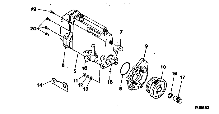
| 000. | [01] | 09000-09462 | PUMP ASSY, INJECTI | 31860-90010 |
| 005. | [01] | 09010-02772 | BODY ASSY, INJECTI | 31860-99012 |
| 006. | [01] | 09080-04020 | GOVERNOR ASSY, MEC | 31860-86040 |
| 007. | [01] | 09001-80081 | COVER, CONTROL RAC | ME702034 |
| 008. | [01] | 90801-30700 | O-RING | ME728818 |
| 009. | [01] | 09006-00031 | COVER SUB-ASSY, TI | |
| 010. | [01] | 09185-10130 | GEAR, TIMER DRIVIN | 09185-10130 |
| 011. | [04] | 94905-02680 | NUT, HEXAGON | ME702046 |
| 012. | [04] | 90258-10001 | WASHER, SPRING | MC327716 |
| 013. | [04] | 94901-15020 | WASHER, STEEL PLAT | MH005068 |
| 014. | [01] | 09009-20100 | BRACKET | ME702036 |
| 015. | [01] | 94913-00050 | KEY, WOODRUFF | ME702747 |
| 016. | [01] | 94901-50500 | WASHER, SPRING | ME008373 |
| 017. | [01] | 09001-20200 | NUT, TIMER ROUND | |
| 018. | [01] | 09210-00830 | PUMP ASSY, FUEL FE | 31860-99020 |
| 019. | [01] | 91410-08201 | BOLT, W/WASHER | |
| 020. | [06] | 94900-50191 | SCREW, SLOTTED FLA | ME022439 |
Include in #3:
09000-09462
as PUMP ASSY, INJECTI
Cross reference number
| Part num | Firm num | Firm | Name |
| 09000-09462 | 31860-9001 | PUMP ASSY, INJECTI |
Information:
1. Rocker Arms and Rocker Shaft
1.1 Disassembly
1 Rocker cover2 Rocker stay bolt3 Rocker arm/rocker shaft assembly4 Snap ring5 Rocker arm6 Rocker stay7 Rocker spring8 Rocker shaft KEY POINTS FOR DISASSEMBLY(1) Removing Rocker Arm/Rocker Shaft Assembly(a) Loosen the rocker arm adjusting screws by approximately one turn each.
Removing rocker stay bolt(b) Remove the rocker stay bolts, then remove the rocker arm/rocker shaft assembly.
Removing rocker arm/rocker shaft assembly(2) Disassembling Rocker Arm/Rocker Shaft AssemblyWhen removing the rocker arms, arrange them in a line matching their installed positions to ensure that they are later refitted in the correct sequence. The rocker arms must be refitted in their original positions to prevent changes in the clearances between the rocker arms and rocker shaft.
Disassembling rocker arm/rocker shaft assembly1.2 Inspection and Repair
Points to check on rocker arm/rocker shaft assembly KEY POINTS FOR INSPECTION AND REPAIR Measuring Rocker Arm-to-Rocker Shaft ClearancesMeasure the rocker arms' inside diameters and the rocker shaft's outside diameter, and calculate the clearances from the measurements. Replace any rocker arm where the clearance exceeds the specified limit.
Unit: mm (in.)
Measuring rocker arm inside diameter and rocker shaft outside diameter1.3 Assembly
Tightening torques and oil application locationsPerform assembly by following the disassembly sequence in reverse: KEY POINTS FOR ASSEMBLY(1) Assembling Rocker Arm/Rocker Shaft AssemblyInstall each pair of rocker arms such that the identification mark (a hole with a diameter of 3 mm (0.12 in.)) is positioned on the side closer to the front of the engine.
Rocker shaft identification mark(2) Adjusting Valve Clearances(a) Loosen the rocker arm nut, then adjust the clearance to the standard value using the adjusting screw and a thickness gauge.
Unit: mm (in.)(b) Hold the adjusting screw in position while tightening the nut.
When adjusting the valve clearances after performing disassembly and reassembly, turn the crankshaft two or three times then check again that the clearances are within specification.
Adjusting valve clearance2. Cylinder Head and Valves
2.1 Disassembly
Cylinder head and valve disassembly sequence1 Push rod2 Main bolt3 Sub-bolt4 Cylinder head5 Cylinder head gasket6 Valve retainer lock7 Retainer8 Valve spring9 Valve (intake/exhaust)10 Valve stem seal11 Valve guide (Remove if it appears defective.) KEY POINTS FOR DISASSEMBLY(1) Removing Cylinder Head(a) Withdraw the push rods.
Withdrawing push rods(b) Loosen the cylinder head bolts in the sequence shown in the drawing. Go through the sequence two or three times, loosening the bolts a little each time. Do not completely remove any bolt in isolation. In the event of a cylinder head fault, use a torque wrench to check the bolts for looseness before deciding to remove them.
Cylinder head bolt loosening sequence(c) Lift the cylinder head assembly straight upward to remove it. If the cylinder head gasket sticks to the cylinder head assembly and cylinder block and prevents them from being separated, tap the thickest parts on the sides of the cylinder head using a plastic-faced hammer.
Removing cylinder head assembly(2) Removing Valves and Valve Springs(a) Use a valve lifter (commercially available) to compress the valve spring, then remove the valve lock.(b) Remove the retainer, spring, and valve. Keep together the valves and other parts