Information pump assy, injecti
Rating:
Components :
| 001. | PUMP ASSY, INJECTI | 09000-09444 |
| 002. | BODY ASSY, INJECTI | 09010-02772 |
| 003. | GOVERNOR ASSY, MEC | 09080-03771 |
| 004. | TIMER ASSY, AUTOMA | 09180-00771 |
| 005. | PUMP ASSY, FUEL FE | 09210-00830 |
Scheme ###:
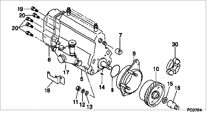
| 000. | [01] | 09000-09444 | PUMP ASSY, INJECTI | 31860-96034 |
| 005. | [01] | 09010-02772 | BODY ASSY, INJECTI | 31860-99012 |
| 006. | [01] | 09080-03771 | GOVERNOR ASSY, MEC | 31860-86010 |
| 007. | [01] | 09001-80081 | COVER, CONTROL RAC | ME702034 |
| 008. | [01] | 90801-30700 | O-RING | ME728818 |
| 009. | [01] | 09006-00021 | COVER SUB-ASSY, TI | 31860-90200 |
| 010. | [01] | 09180-00771 | TIMER ASSY, AUTOMA | |
| 011. | [04] | 94905-02680 | NUT, HEXAGON | ME702046 |
| 012. | [04] | 90258-10001 | WASHER, SPRING | MC327716 |
| 013. | [04] | 94901-15020 | WASHER, STEEL PLAT | MH005068 |
| 014. | [01] | 94913-00050 | KEY, WOODRUFF | ME702747 |
| 015. | [01] | 94901-50500 | WASHER, SPRING | ME008373 |
| 016. | [01] | 09001-20200 | NUT, TIMER ROUND | |
| 017. | [01] | 09210-00830 | PUMP ASSY, FUEL FE | 31860-99020 |
| 018. | [01] | 09009-20100 | BRACKET | ME702036 |
| 019. | [01] | 91518-08221 | BOLT, W/WASHER | MM500963 |
| 020. | [06] | 94900-50191 | SCREW, SLOTTED FLA | ME022439 |
| 030. | [01] | 09243-60180 | COUPLING, INJECTIO | 31860-90300 |
Include in #3:
09000-09444
as PUMP ASSY, INJECTI
Cross reference number
| Part num | Firm num | Firm | Name |
| 09000-09444 | 31860-9603 | PUMP ASSY, INJECTI |
Information:
Engine overhauls necessitate removing accessories (auxiliary equipment). This group contains procedures and important points for removal and installation of accessories.1. Preparatory Operations
(a) Stop the fuel supply and disconnect the starting system.(b) Loosen the drain cocks at the rear of the left- and right-hand sides of the crankcase and allow the coolant to drain out.(c) Loosen the drain plug on the oil pan and allow the engine oil to drain out. (Oil pan capacity: 100 liters (26.4 U.S. gallons))
Hot oil can inflict severe burns. Be careful not to touch it.
2. Removing Accessories
(1) Removing Fan(a) Reduce the tension applied by the tension pulley by pushing the alternator toward the engine, then remove the water pump drive belt (1).(b) Remove the fan mounting bolts (2), then remove the fan (3).(c) Remove the water pump pulley (4), which was previously retained by the fan mounting bolts (2).(2) Removing Thermostat FittingRemove the water outlet fitting (1), then remove the thermostat (2), thermostat fitting (3), water joint (4), and temperature joint (5) in that sequence. (3) Removing Exhaust and Intake Manifolds(a) Remove the exhaust manifold mounting bolts, then remove the exhaust manifold (1) and the gasket (2).(b) Remove the intake manifold mounting bolts, then remove the intake manifold (3) and the gasket (4). When refitting the manifolds, fit each gasket with the side marked "MANIFOLD" facing the manifold. (4) Removing Water PumpRemove the water pump mounting bolts, then remove the water pump (1). (5) Removing Alternator(a) Disconnect the battery cables.(b) Disconnect the lead from terminal B at the rear of the alternator.(c) Remove the alternator connector.(d) Loosen the alternator brace bolt (1) and support bolt (2), then push the alternator toward the engine and remove the fan belt.(e) Remove the alternator. (6) Removing Starter(a) Disconnect the battery's (-) and (+) terminals in that sequence.(b) Disconnect the start wiring (1).(c) Remove the starter's two mounting bolts (2), then remove the starter (3). (7) Removing Oil Filter(a) The oil filter (2) must be replaced every 100 hours of use.(b) Remove the oil filter using a filter wrench (1). (8) Removing Fuel Filter(a) Remove the fuel pipe (1) that leads from the fuel tank and the fuel pipe (2) that leads to the fuel pump.(b) Remove the fuel filter (3) from the engine. (9) Removing Fuel Pipes(a) Remove the clamps from the four fuel pipes (1), then disconnect the fuel pipes from the engine and from the injection pump.(b) Remove the joints and clips from the fuel hose (2), then disconnect the fuel hose from the injector holders.
To keep dirt out of the fuel system, fit rubber caps over the parts of the injection pump and injector inlet connectors from which the injection pipes are disconnected.
(10) Removing Injection Pump
1 Fuel hose2 Fuel pipe3 Tie rod cover4 Tie rod spring5 Tie rod6 Injection pump7 Adjustment shim8 Control rack pin(a) Remove the tie rod cover (3).
Removing tie rod cover(b) Using long-nosed pliers, remove the tie rod spring (4) from the control rack pin (8) and from the governor lever