Information pump assy, injecti
Rating:
Components :
| 001. | PUMP ASSY, INJECTI | 09000-09434 |
| 002. | BODY ASSY, INJECTI | 09010-02772 |
| 003. | GOVERNOR ASSY, MEC | 09080-03771 |
| 004. | TIMER ASSY, AUTOMA | 09180-00781 |
| 005. | PUMP ASSY, FUEL FE | 09210-00830 |
Scheme ###:
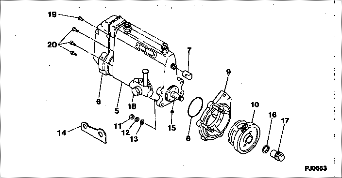
| 000. | [01] | 09000-09434 | PUMP ASSY, INJECTI | 31860-91034 |
| 005. | [01] | 09010-02772 | BODY ASSY, INJECTI | 31860-99012 |
| 006. | [01] | 09080-03771 | GOVERNOR ASSY, MEC | 31860-86010 |
| 007. | [01] | 09001-80081 | COVER, CONTROL RAC | ME702034 |
| 008. | [01] | 90801-30700 | O-RING | ME728818 |
| 009. | [01] | 09006-00031 | COVER SUB-ASSY, TI | |
| 010. | [01] | 09180-00781 | TIMER ASSY, AUTOMA | 31860-99050 |
| 011. | [04] | 94905-02680 | NUT, HEXAGON | ME702046 |
| 012. | [04] | 90258-10001 | WASHER, SPRING | MC327716 |
| 013. | [04] | 94901-15020 | WASHER, STEEL PLAT | MH005068 |
| 014. | [01] | 09009-20100 | BRACKET | ME702036 |
| 015. | [01] | 94913-00050 | KEY, WOODRUFF | ME702747 |
| 016. | [01] | 94901-50500 | WASHER, SPRING | ME008373 |
| 017. | [01] | 09001-20200 | NUT, TIMER ROUND | |
| 018. | [01] | 09210-00830 | PUMP ASSY, FUEL FE | 31860-99020 |
| 019. | [01] | 91518-08221 | BOLT, W/WASHER | MM500963 |
| 020. | [06] | 94900-50191 | SCREW, SLOTTED FLA | ME022439 |
Include in #3:
09000-09434
as PUMP ASSY, INJECTI
Cross reference number
| Part num | Firm num | Firm | Name |
| 09000-09434 | 31860-9103 | PUMP ASSY, INJECTI |
Information:
1. Engine Adjustment
1.1 Inspecting and Adjusting Valve ClearancesThe valve clearances should be inspected and adjusted when the engine is cold.
Unit: mm (in.)Loosen the cylinder head bolts slightly then retighten them to the specified torques.
Adjusting valve clearance
Unit: N*m {kgf*m} (lbf-ft)(1) Inspecting Valve Clearances(a) Inspect each cylinder's valve clearances with the piston at the top-dead-center (TDC) position of its compression stroke. Follow the firing order, bringing the pistons to the TDC positions of their respective compression strokes by turning the crankshaft in the forward direction in increments of 180°.(2) Confirming Compression-Stroke TDC Position(a) Bring piston No. 1 to the TDC position of its compression stroke. To do this, align the TDC mark on the crankshaft pulley with the mark on the gear case.(b) To confirm the compression-stroke TDC position, turn the crankshaft by approximately 20° in the forward and reverse directions and check for rocker-arm movement. When there is no rocker-arm movement, the piston is at the compression-stroke TDC position.(c) If rocker-arm movement occurs, the piston is at the TDC position of its intake or exhaust stroke. Give the crankshaft one more 180° turn to bring the piston to the TDC position of its compression stroke.
Retightening sequence for cylinder head bolts (d) Start bringing the piston to the TDC position with cylinder No. 1 for inspection/adjustment of the valve clearance. Then, proceed to the other cylinders' pistons in accordance with the firing order. After cylinder No. 1, bring the piston in the next cylinder to its compression-stroke TDC position by turning the crankshaft in the forward direction (clockwise as seen from the timing gear case) by 180°.
Before starting the engine, place the timing gears in their original positions.
Timing marks(3) Adjusting Valve Clearances(a) Loosen the rocker arm nut, then adjust the clearance to the standard value using the adjusting screw and a thickness gauge (1).(b) Hold the adjusting screw in position while tightening the nut.
When adjusting the valve clearances following disassembly and reassembly, turn the crankshaft two or three times then check again that the clearances are within specification.
Adjusting valve clearance1.2 Bleeding Air From Fuel SystemAir should be bled first from the fuel filter and then from the injection pump, i.e., starting at the position closer to the fuel tank.(1) With the system with an electromagnetic-plunger-type fuel pump, turn the key to the ON position to force fuel to flow. Then, loosen the air vent screw (1), allow air in the filter to be expelled, and retighten the screw.(2) Loosen air vent screws (2) and (3) on the injection pump in that sequence to bleed air from the fuel pipe and injection pump.(3) When air-bleeding from screws (2) and (3) is complete, retighten each screw.(4) Air in the injection pipes and nozzles will be expelled automatically when the engine is cranked.
Bleeding air from fuel system1.3 Inspecting and Adjusting Injection Timing(1) Preparation for Inspection(a) Close the cock on the fuel filter.(b) Remove the No. 1 injection pipe.(c) Remove the No. 1 delivery valve holder, delivery valve, and spring. Then, refit only the