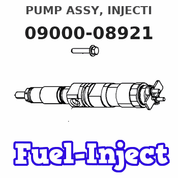
Information pump assy, injecti
Rating:
Components :
| 001. | PUMP ASSY, INJECTI | 09000-08921 |
| 002. | BODY ASSY, INJECTI | 09010-02291 |
| 003. | COVER, BEARING | 09020-10053 |
| 004. | GOVERNOR ASSY, MEC | 09080-02692 |
| 005. | TIMER ASSY, AUTOMA | 09180-00670 |
| 006. | PUMP ASSY, FUEL FE | 09210-00412 |
| 007. | COUPLING ASSY | 09250-00192 |
Scheme ###:
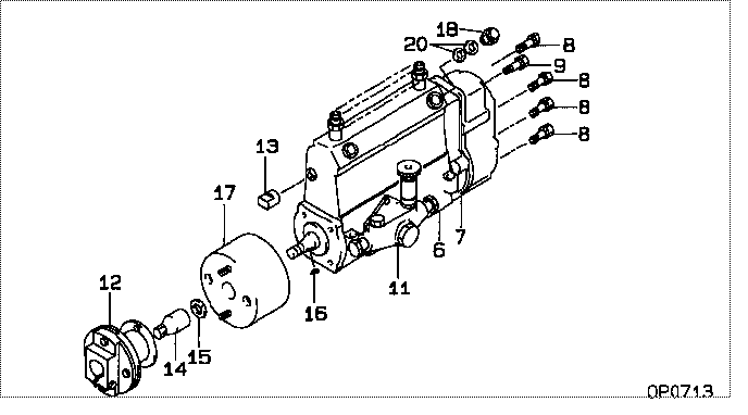
| 000. | [01] | 09000-08921 | PUMP ASSY, INJECTI | 22100-1340 |
| 006. | [01] | 09010-02291 | BODY ASSY, INJECTI | 22110-1470 |
| 007. | [01] | 09080-02692 | GOVERNOR ASSY, MEC | 22310-1690 |
| 008. | [06] | 94904-71150 | BOLT, W/WASHER | 6 306 1001 00 |
| 009. | [01] | 94904-73910 | BOLT, W/WASHER | 22815-2820A |
| 011. | [01] | 09210-00412 | PUMP ASSY, FUEL FE | 6 302 1500 11 |
| 012. | [01] | 09250-00192 | COUPLING ASSY | 22630-1010A |
| 013. | [01] | 09001-80120 | COVER, CONTROL RAC | 22371-1170A |
| 014. | [01] | 09001-20010 | NUT, TIMER ROUND | 22353-1050A |
| 015. | [01] | 90258-12001 | WASHER, SPRING | 22873-1310A |
| 016. | [01] | 94913-00050 | KEY, WOODRUFF | 22891-1040A |
| 017. | [01] | 09180-00670 | TIMER ASSY, AUTOMA | 22510-1360 |
| 018. | [01] | 09031-00130 | VALVE ASSY, OVERFL | 22107-1090A |
| 020. | [02] | 94901-02480 | WASHER | 22847-1940A |
Include in #3:
09000-08921
as PUMP ASSY, INJECTI
Cross reference number
| Part num | Firm num | Firm | Name |
| 09000-08921 | 22100-1340 | PUMP ASSY, INJECTI |
Information:
PREPARATION FOR DISASSEMBLY
1. Engine oil draining Remove the drain plug from the bottom of the oil pan and allow the oil to drain. 2. Coolant draining Loose the drain plug on the right side of the cylinder block and allow the coolant to drain. ELECTRICAL SYSTEM
1. Starter 1.1. Testing before disassembly(1) Clearance between pinion and housing (pinion clearance)(a) Connect the starter to a 12 volt battery as shown in the illustration to cause the pinion to shift into cranking position and remain there.
Due to the amount of current being passed through the solenoid series winding, this test must be made within 10 seconds.
(b) Push the pinion toward the commutator end by hand to measure its free movement (pinion clearance). (c) The pinion clearance must be 0.5 to 2.0 mm (0.020 to 0.079 in.). If the clearance is out of this range, make an adjustment to it by adding or removing the packings on the magnetic switch. Adding the packings will decrease the clearance.
Connections for measuring pinion clearance(2) No-load characteristics (a) Connect the starter to a 12 volt battery with an ammeter capable of indicating several hundred amperes as shown in the illustration.(b) Close the switch to make sure the pinion shifts into cranking position properly and the starter runs at speeds higher than is specified. If the current draw and/or operating speed is out of the standard, disassemble the starter for inspection and repairs.
Connections for testing no-load characteristics
a) The size of wires used for this test must be as large as possible. Tighten the terminals securely.b) This starter has a reduction gear. Do not confuse gear noise with some abnormal noise else. c) When measuring the starter speed at the end of the pinion, be ready for accidental shifting of the pinion.
(3) Magnetic switch(a) Disconnect the connector from the M terminal of the magnetic switch. (b) Connect the magnetic switch to a 12 volt battery with a switch as shown in the illustration to test the pull-in coil. Close the switch to see if the pinion shifts. If the piston fails to shift, the magnetic switch is faulty.
Due to the amount of current being passed through the solenoid series winding, this test must be made within 10 seconds.
(c) Connect the magnetic switch to a 12 volt battery with a switch as shown in the illustration to test the hold-in coil. Close the switch and pull the pinion away from the commutator end by hand. Release the pinion to see if it remains there.