Information pump assy, injecti

Rating:
Components :
| 001. | PUMP ASSY, INJECTI | 09000-07981 |
| 002. | BODY ASSY, INJECTI | 09010-02690 |
| 003. | COVER, BEARING | 09020-10053 |
| 004. | GOVERNOR ASSY, MEC | 09080-03670 |
| 005. | TIMER ASSY, AUTOMA | 09180-00390 |
| 006. | PUMP ASSY, FUEL FE | 09210-00412 |
| 007. | COUPLING ASSY | 09240-00043 |
Scheme ###:
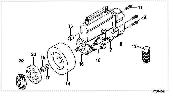
| 000. | [01] | 09000-07981 | PUMP ASSY, INJECTI | 6 074 1106 10 |
| 007. | [01] | 09010-02690 | BODY ASSY, INJECTI | |
| 008. | [01] | 09080-03670 | GOVERNOR ASSY, MEC | |
| 009. | [06] | 94900-50191 | SCREW, SLOTTED FLA | 6 056 1305 60 |
| 011. | [01] | 91518-08221 | BOLT, W/WASHER | 22815-1190A |
| 013. | [01] | 09001-80220 | COVER, CONTROL RAC | 22114-1050A |
| 014. | [01] | 09180-00390 | TIMER ASSY, AUTOMA | 22510-1330A |
| 015. | [01] | 09001-20010 | NUT, TIMER ROUND | 22353-1050A |
| 016. | [01] | 94913-00050 | KEY, WOODRUFF | 22891-1040A |
| 017. | [01] | 90258-12001 | WASHER, SPRING | 22873-1310A |
| 018. | [01] | 09210-00412 | PUMP ASSY, FUEL FE | 6 302 1500 11 |
| 019. | [01] | 09006-10011 | COVER, PRIMING PUM | 6 053 1552 60 |
| 022. | [01] | 09240-00043 | COUPLING ASSY | 22610-1090A |
| 023. | [01] | 09243-60040 | COUPLING, INJECTIO | 22612-1100A |
Include in #3:
09000-07981
as PUMP ASSY, INJECTI
Cross reference number
| Part num | Firm num | Firm | Name |
| 09000-07981 | 6 074 1106 | PUMP ASSY, INJECTI |
Information:
Fan Belt
Removal
Fig. 1-Cap Screw and BoltLoosen cap screw and alternator mounting bolt (Fig. 1). Move alternator so fan belt can be moved off pulley. Remove fan belt.Repair
Inspect belts for:1 Cracking2 Rupture3 Tears4 Burning5 Gouging6 Wear7 Internal Cord Failure8 Cuts9 Peeling, Fraying, ChewingDo not reuse a damaged belt. Install a new belt.Installation
Fig. 2-Install Fan BeltPut fan belt over fan (1, Fig. 2). Put fan belt over crankshaft pulley (2) and alternator pulley (3). Position fan belt in pulley grooves.Adjust fan belt tension (Group 9010).Crankshaft Pulley
Removal
Remove fan belt from pulley (Group 0429).
Fig. 3-Cap Screw and WasherRemove cap screw and washer (Fig. 3) holding crankshaft pulley on crankshaft. IMPORTANT: On six cylinder engines the crankshaft pulley is also a vibration damper. Do not drop or hammer on vibration dampers.
Fig. 4-D01200AA PullerUsing D01200AA Puller (Fig. 4), pull crankshaft pulley off crankshaft.Repair
Inspect pulley sheaves for cracks and wear. Replace pulley if damaged.For vibration damper repair, see Group 0401.Installation
Position crankshaft pulley on crankshaft.Put washer on cap screw. Install cap screw through crankshaft pulley into crankshaft.
Fig. 5-Cap ScrewTighten cap screw (Fig. 5) to 85 lb-ft (115 N m) (12 kg-m).Install fan belts (Group 0429).Adjust fan belt tension (Group 9010).
Removal
Fig. 1-Cap Screw and BoltLoosen cap screw and alternator mounting bolt (Fig. 1). Move alternator so fan belt can be moved off pulley. Remove fan belt.Repair
Inspect belts for:1 Cracking2 Rupture3 Tears4 Burning5 Gouging6 Wear7 Internal Cord Failure8 Cuts9 Peeling, Fraying, ChewingDo not reuse a damaged belt. Install a new belt.Installation
Fig. 2-Install Fan BeltPut fan belt over fan (1, Fig. 2). Put fan belt over crankshaft pulley (2) and alternator pulley (3). Position fan belt in pulley grooves.Adjust fan belt tension (Group 9010).Crankshaft Pulley
Removal
Remove fan belt from pulley (Group 0429).
Fig. 3-Cap Screw and WasherRemove cap screw and washer (Fig. 3) holding crankshaft pulley on crankshaft. IMPORTANT: On six cylinder engines the crankshaft pulley is also a vibration damper. Do not drop or hammer on vibration dampers.
Fig. 4-D01200AA PullerUsing D01200AA Puller (Fig. 4), pull crankshaft pulley off crankshaft.Repair
Inspect pulley sheaves for cracks and wear. Replace pulley if damaged.For vibration damper repair, see Group 0401.Installation
Position crankshaft pulley on crankshaft.Put washer on cap screw. Install cap screw through crankshaft pulley into crankshaft.
Fig. 5-Cap ScrewTighten cap screw (Fig. 5) to 85 lb-ft (115 N m) (12 kg-m).Install fan belts (Group 0429).Adjust fan belt tension (Group 9010).