Information pump assy, injecti
Rating:
Components :
| 001. | PUMP ASSY, INJECTI | 09000-07281 |
| 002. | SWITCH KIT, CONTRO | 09009-90090 |
| 003. | BODY ASSY, INJECTI | 09010-02210 |
| 004. | COVER, BEARING | 09020-10053 |
| 005. | TIMER ASSY, AUTOMA | 09180-00560 |
| 006. | PUMP ASSY, FUEL FE | 09210-00082 |
| 007. | COUPLING ASSY | 09240-00043 |
Scheme ###:
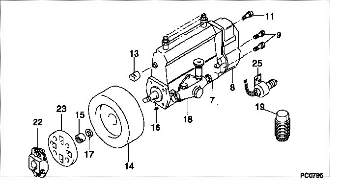
| 000. | [01] | 09000-07281 | PUMP ASSY, INJECTI | 6 074 1011 60 |
| 007. | [01] | 09010-02210 | BODY ASSY, INJECTI | 6 075 1203 20 |
| 008. | [01] | 09130-00034 | GOVERNOR ASSY, MEC | 22310-1800 |
| 009. | [06] | 94904-71150 | BOLT, W/WASHER | 6 306 1001 00 |
| 011. | [01] | 91518-08221 | BOLT, W/WASHER | 22815-1190A |
| 013. | [01] | 09001-80090 | COVER, CONTROL RAC | 22114-1250A |
| 014. | [01] | 09180-00560 | TIMER ASSY, AUTOMA | 22510-1440 |
| 015. | [01] | 09001-20010 | NUT, TIMER ROUND | 22353-1050A |
| 016. | [01] | 94913-00050 | KEY, WOODRUFF | 22891-1040A |
| 017. | [01] | 90258-12001 | WASHER, SPRING | 22873-1310A |
| 018. | [01] | 09210-00082 | PUMP ASSY, FUEL FE | 22570-1180 |
| 019. | [01] | 09006-10011 | COVER, PRIMING PUM | 6 053 1552 60 |
| 022. | [01] | 09240-00043 | COUPLING ASSY | 22610-1090A |
| 023. | [01] | 09243-60020 | COUPLING, INJECTIO | 22612-1020A |
| 025. | [01] | 09009-90090 | SWITCH KIT, CONTRO | 22690-1180A |
Include in #3:
09000-07281
as PUMP ASSY, INJECTI
Cross reference number
| Part num | Firm num | Firm | Name |
| 09000-07281 | 6 074 1011 | PUMP ASSY, INJECTI |
Information:
941B 80H3884-Up
(1) Remove the engine from the machine; see the Service Manual for the procedure. Put both engines, new and old, in a position that will give good access to their front, rear, top and both sides. For those engines that were equipped with glow plugs, either remove the wire from the heat-start switch to the glow plug lead assembly, or put tape over the end of the wire when it is disconnected. This wire will not be needed because the new engine does not have glow plugs.(2) From the old engine, remove the crankshaft pulley and hub, engine front support, the rear supports (from the sides of the flywheel housing) and the flywheel. Install these
(1) Remove the engine from the machine; see the Service Manual for the procedure. Put both engines, new and old, in a position that will give good access to their front, rear, top and both sides. For those engines that were equipped with glow plugs, either remove the wire from the heat-start switch to the glow plug lead assembly, or put tape over the end of the wire when it is disconnected. This wire will not be needed because the new engine does not have glow plugs.(2) From the old engine, remove the crankshaft pulley and hub, engine front support, the rear supports (from the sides of the flywheel housing) and the flywheel. Install these