Information pump assy, injecti
Nozzle:
0935001320
Rating:
KIT List:
| Pump assy, fuel fe | 1922900060 |
Components :
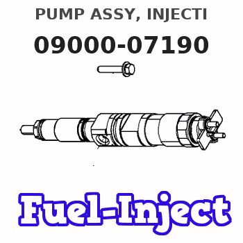
| 001. | PUMP ASSY, INJECTI | 09000-07190 |
| 002. | BODY ASSY, INJECTI | 09010-01091 |
| 003. | PUMP ASSY, FUEL FE | 09210-00372 |
Scheme ###:
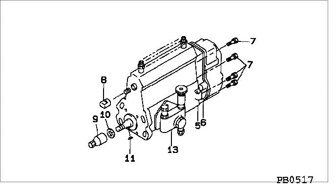
| 000. | [01] | 09000-07190 | PUMP ASSY, INJECTI | 31661-00014 |
| 005. | [01] | 09010-01091 | BODY ASSY, INJECTI | 31361-10101 |
| 006. | [01] | 09080-03020 | GOVERNOR ASSY, MEC | 31661-00503 |
| 007. | [06] | 94904-70620 | BOLT, W/WASHER | ME703359 |
| 008. | [01] | 09001-80081 | COVER, CONTROL RAC | ME702034 |
| 009. | [01] | 09001-20260 | NUT, TIMER ROUND | ME703450 |
| 009. | [01] | 09001-20080 | NUT, TIMER ROUND | ME022426 |
| 010. | [01] | 94901-50500 | WASHER, SPRING | ME008373 |
| 011. | [01] | 94913-00160 | KEY, WOODRUFF | ME022425 |
| 013. | [01] | 09210-00372 | PUMP ASSY, FUEL FE | ME02082701 |
Include in #3:
09000-07190
as PUMP ASSY, INJECTI
Cross reference number
| Part num | Firm num | Firm | Name |
| 09000-07190 | 31661-0001 | PUMP ASSY, INJECTI | |
| 31661-00014 | MITSUBISHI | PUMP ASSY, INJECTI |
Information:
Fuel Injection Pump
Removal
IMPORTANT: Never steam clean or pour cold water on an injection pump while the pump is running or while it is warm.Clean the injection pump, lines, and area around the pump with cleaning solvent or a steam cleaner.
Fig. 1-Timing MarkUse JD-281 or JDE-81-1 Flywheel Turning Tool to position number one piston at top dead center. When the timing pin is inserted in the hole in the flywheel and the timing mark (A, Fig. 1) is visible on the injection pump governor weight retainer, the number one piston is at top dead center on the compression stroke.3-179D Engine (ROTO-DIESEL Fuel Injection Pump)
Fuel Injection Pump Only
Escaping diesel fuel under pressure can have sufficient force to penetrate the skin causing serious personal injury.If injured by escaping fuel, see a doctor at once. Serious infection or reaction can develop if proper medical treatment is not administered immediatetly.
Fig. 2-Loosen Injection Lines at NozzlesTo relieve high pressure in the fuel system, slightly loosen fuel injection line connections at each injection nozzle with two wrenches (Fig. 2).
Fig. 3-ROTO-DIESEL Fuel Injection Pump RemovalDisconnect throttle linkage (B, Fig. 3) and electric shut-off wire (C).Disconnect fuel return line (A) and fuel supply line (D). IMPORTANT: When removing injection lines, DO NOT turn pump outlet fittings. Turning these fittings may damage pump internally.Disconnect injection lines (E).Close all openings with caps and plugs.Remove injection pump gear cover from timing cover.Remove drive gear attaching nut from injection pump shaft and spring washer.
Fig. 4-Fuel Injection Pump Removal 1 -Nut2 -Cap Screw3 -Cap ScrewAttach special took KJD-10108 to timing gear housing (Fig. 4).Remove three hex nuts (F, Fig. 3).Turn cap screw of special tool clockwise until pump shaft is loosened from drive gear. When removing fuel injection pump, be careful not to lose pump shaft Woodruff key.Remove fuel injection pump.Remove special tool KJD-0108.3-164D, 4-219D, 4-239D, 4-276D, 6-329D or 6-359D Engine (ROOSA-MASTER Model JDB)
Fuel Injection Pump OnlyPosition crankshaft so that number one piston is at top dead center on compression stroke.
Escaping diesel fuel under pressure can have sufficient force to penetrate the skin causing serious personal injury.If injured by escaping fuel, see a doctor at once. Serious infection or reaction can develop if proper medical treatment is not administered immediately.
Fig. 5-Loosen Injection Lines at NozzlesTo relieve high pressure in the fuel system, slightly loosen fuel injection line connections at each injection nozzle with two wrenches (Fig. 5).
Fig. 6-Fuel Injection Pump RemovalDisconnect fuel supply line (1, Fig. 6), fuel return line (2), and fuel injection lines (3). Plug or cap all openings.Disconnect throttle linkage and wire throttle lever (4) in high idle position.Remove nuts (5) attaching injection pump to engine front plate.Slide pump in a straight line away from the front plate.Injection pump drive gear and shaft will remain on front plate. Injection Pump Drive ShaftRemove injection pump (Group 0413).Remove injection pump gear cover.
Fig. 7-Drive Shaft RemovalRemove thrust pin (1, Fig. 7) and thrust spring.Remove nut (2) from the end of the drive shaft.
Fig. 8-JD303-Injection Pump Shaft Removal ToolInstall JD303 Injection Pump Shaft