Information pump assy, injecti
Rating:
Components :
| 001. | PUMP ASSY, INJECTI | 09000-06403 |
| 002. | BODY ASSY, INJECTI | 09010-01702 |
| 003. | COVER, BEARING | 09020-10110 |
| 004. | TIMER ASSY, AUTOMA | 09180-00431 |
| 005. | PUMP ASSY, FUEL FE | 09210-01900 |
| 006. | COUPLING ASSY | 09250-00151 |
Scheme ###:
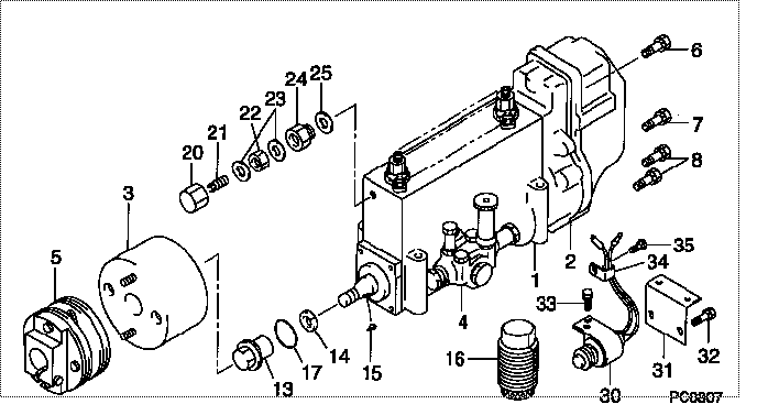
| 000. | [01] | 09000-06403 | PUMP ASSY, INJECTI | 6 074 1013 51 |
| 001. | [01] | 09010-01702 | BODY ASSY, INJECTI | 22110-1440A |
| 002. | [01] | 09130-00302 | GOVERNOR ASSY, MEC | 22310-1620 |
| 003. | [01] | 09180-00431 | TIMER ASSY, AUTOMA | 22510-1580A |
| 004. | [01] | 09210-01900 | PUMP ASSY, FUEL FE | 22570-1330A |
| 005. | [01] | 09250-00151 | COUPLING ASSY | 22610-1140A |
| 006. | [02] | 91518-06161 | BOLT, W/WASHER | 22815-1310A |
| 007. | [02] | 94900-50191 | SCREW, SLOTTED FLA | 6 056 1305 60 |
| 008. | [04] | 94904-10131 | BOLT, SLOTTED HEXA | 22861-1250 |
| 013. | [01] | 09001-20230 | NUT, TIMER ROUND | 22825-1110A |
| 014. | [01] | 94901-40070 | WASHER, COUNTERSUN | 22877-1190A |
| 015. | [01] | 90458-05750 | KEY, WOODRUFF | 22891-1070A |
| 016. | [01] | 09006-10011 | COVER, PRIMING PUM | 6 053 1552 60 |
| 017. | [01] | 90801-40280 | O-RING | 22817-1050A |
| 020. | [01] | 09003-20040 | CAP | 22342-1110A |
| 021. | [01] | 09002-60050 | SCREW, ADJUSTING | 22396-1140A |
| 022. | [01] | 94805-30100 | NUT, HEXAGON, W/HO | 22885-3830A |
| 023. | [02] | 94901-80350 | WASHER, COPPER PLA | 22847-1950A |
| 024. | [01] | 09001-80152 | COVER, CONTROL RAC | 22372-1100A |
| 025. | [01] | 94901-80710 | WASHER, COPPER PLA | 22863-1300A |
| 030. | [01] | 09009-00100 | SWITCH SUB-ASSY, C | 6 051 5627 00 |
| 031. | [01] | 09009-20031 | BRACKET | 22343-1030A |
| 032. | [02] | 94904-71360 | BOLT, W/WASHER | 22815-2500A |
| 033. | [02] | 91518-05121 | BOLT, W/WASHER | 22815-1110A |
| 034. | [01] | 94935-00460 | CLIP, CORD | 22682-1050 |
| 035. | [01] | 91510-05081 | BOLT, W/WASHER | 22815-1350A |
Include in #3:
09000-06403
as PUMP ASSY, INJECTI
Cross reference number
| Part num | Firm num | Firm | Name |
| 09000-06403 | 6 074 1013 | PUMP ASSY, INJECTI |
Information:
Removal
Remove cylinder head (Group 0409).Install short cap screws with large flat washers to hold cylinder liners down.Remove ridge or carbon from cylinder liners using a ridge reamer.Remove oil pan (Group 0407). Do not use pneumatic wrench to remove connecting rod cap screws.Remove connecting rod cap screws.Measure connecting rod bearing-to-crankshaft rod journal clearance.
Fig. 1-Connecting Rod Bearing Measurement
Fig. 2-Connecting Rod Bore I.D.
Fig. 3-Oil ClearanceConnecting rod bearing to crankshaft oil clearance (new) Fig. 3 ... 0.001 to 0.005 inch(0.025 to 0.127 mm)Connecting rod bearing to crankshaft oil clearance (maximum) (Fig. 3) ... 0.006 inch(0.152 mm)Mark pistons for re-installation in same bore from which they are removed.Push pistons out top of the cylinder liners.Repair
Pistons
See Group 0404 for piston-to-cylinder liner measurements.Remove piston rings. IMPORTANT: Do not soak pistons more than 60 minutes.
Avoid contact of solution with skin or eyes.
Soak pistons in 50 percent solution of "Mr. Clean" (or equivalent) and water for 30 to 60 minutes. IMPORTANT: Never clean pistons with wire brush or abrasives.Scrub piston with stiff bristle brush.Rinse pistons in clean water and dry with clean towels. Two different types of pistons marked "B" and "H" on their top face can be selectively installed on 3179D, 4239 D & T, and 6359 D & T engines for a better dead space control inside the cylinder. The difference between the two pistons is 0.006 inch (0.15 mm) on the distance between the piston pin center and the piston top.When replacing pistons, install pistons of the same type as the original.When replacing cylinder block or when mark on piston is no longer visible, determine piston type as follows using gauge KCD-10003.Install cylinder liners and crankshaft with bearings in cylinder block.Secure cylinder liners, using cap screws and washers.Install a "B" type piston with its connecting rod and secure with cap.
Fig. 3A-Determining Type of Piston Using Gauge KCD-10003Place gauge KCD-10003 on liner flange and press downward (3A).Turn crankshaft until piston is in "TDC" position.When piston lightly touches gauge then use "B" type pistons.When pisotn does not contact gauge, then use "H" type pistons.If no gauge is available, proceed as follows:Install a "B" type piston with its connecting rod and secure with cap.Using a dial indicator measure protrusion of each piston (at TDC) above face of cylinder block. Measure at cylinder block centerlineInstall a "B" type piston if protrusion is above or equal to 0.004 in. (0.1 mm) and an "H" type piston if protrusion is below 0.004 in. (0.1 mm). IMPORTANT: Maximum allowable piston standout is 0.012 in. (0.30 mm).Piston Rings and Ring Grooves
Do not re-use piston rings.
Fig. 4-JDE-62 Ring Groove Wear GaugeUsing JDE-62 Ring Groove Wear Gauge (Fig. 4), measure top ring groove. If gauge shoulders contact the ring land, groove is excessively worn.Measure rectangular ring grooves with proper new ring and a feeler gauge.
Fig. 5-Measure Ring GroovesRing groove clearance (maximum) (Fig. 5) ... 0.008 inch(0.20 mm)Piston Pin Bore
Fig. 6-Piston Pin AssemblyPiston pins must fit piston pin bore with a thumb press fit (Fig. 6).Replace piston if piston pin bore is