Information pump assy, injecti
Rating:
Components :
| 001. | PUMP ASSY, INJECTI | 09000-03661 |
| 001. | PUMP ASSY, INJECTI | 09000-03661 |
| 002. | BODY ASSY, INJECTI | 09010-01400 |
| 003. | GOVERNOR ASSY, MEC | 09080-01281 |
| 004. | GOVERNOR ASSY, MEC | 09080-02680 |
Scheme ###:
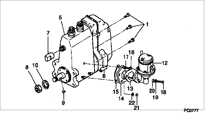
| 000. | [01] | 09000-03660 | PUMP ASSY, INJECTI | 34161-50290 |
| 000. | [01] | 09000-03661 | PUMP ASSY, INJECTI | 34161-50291 |
| 001. | [06] | 94904-70620 | BOLT, W/WASHER | |
| 005. | [01] | 09010-01400 | BODY ASSY, INJECTI | |
| 006. | [01] | 09080-01281 | GOVERNOR ASSY, MEC | |
| 006. | [01] | 09080-02680 | GOVERNOR ASSY, MEC | |
| 007. | [01] | 09001-80061 | COVER, CONTROL RAC | 09001-80061 |
| 008. | [01] | 94905-02450 | NUT, HEXAGON | 94905-02450 |
| 009. | [01] | 94913-00190 | KEY, WOODRUFF | |
| 010. | [01] | 94901-50500 | WASHER, SPRING | 94901-50500 |
| 012. | [01] | 09210-05000 | PUMP ASSY, FUEL FE | 34061-50130 |
| 013. | [01] | 09223-70020 | GASKET | 09223-70020 |
| 014. | [01] | 09223-60020 | SPACER | 09223-60020 |
| 015. | [01] | 09010-60040 | GASKET, FEED PUMP | 09010-60040 |
| 018. | [02] | 90128-08201 | BOLT, HEXAGON | 90128-08201 |
| 019. | [02] | 90258-08001 | WASHER, SPRING | CSA915D100 |
| 020. | [02] | 09241-70010 | WASHER, COUPLING S | 09241-70010 |
| 021. | [02] | 90160-06051 | NUT, HEXAGON | 85265-00085 |
| 022. | [02] | 90258-06001 | WASHER, SPRING | 90258-06001 |
Include in #3:
09000-03661
as PUMP ASSY, INJECTI
Cross reference number
| Part num | Firm num | Firm | Name |
| 09000-03661 | 34161-5029 | PUMP ASSY, INJECTI |
Information:
Timing Light
1P3500 And 2P8280 Timing Lights - Electrical Schematic, Test Points And Parts List
Inverter - Electrical Schematic, Test Points And Parts List
There is a two position switch that is marked ADV.-RPM on the side of the 1P3499 Timing Light. When the timing light is in use, operation of the ADV.-RPM switch is as follows:RPM Position
A fuel injection pulse opens the switch in the transducer and starts a positive pulse (TP9) of fixed duration, from the monostable composed of Q2 and Q3. This pulse turns on a transistor switch Q4, allowing current to pass through meter M1, which mechanically averages pulses from an operating engine, and is calibrated to read RPM. Switch S2 grounds the gate of SCR1 to prevent the flash tube from strobing.ADV. Position
A fuel injection pulse again starts a pulse from the monostable. Adjustment of R7, the TIME-ADVANCE control, now determines the pulse duration from the monostable. When R7 is adjusted so that TDC on the damper coincides with the pointer on the block of an operating engine, the monostable pulse duration is exactly the same as the fuel system advance measured in seconds. Transistor switch Q4 again turns on, allowing current to pass through meter M1, causing a meter indicator that is calibrated in degrees of advance instead of seconds.Electrical Calibration Procedure
Before the electrical calibration can be done, the following equipment must be obtained.1) Oscilloscope with triggered sweep. Heath Co. M/N SO-4530 or equivalent.2) Signal generator. Heath M/N SG-72A or equivalent.3) Electronic counter. Data Precision M/N 5740 or equivalent.4) Electronic switch (dealer built).Calibration Procedure
(1) Hold the 1P3499 Timing Light in the same position (about a 45° angle) as if measuring the timing advance on an engine, and check the mechanical meter zero. Make an adjustment to zero if necessary. (2) To remove the protective rubber boot from the flash tube, twist the rubber boot and pull it away from the timing light as shown. (3) Remove the right side (side that has the serial number tag) of the timing light case.(4) Connect the 1P3499 Timing Light to a circuit like the one that follows. This will simulate (be the same as) a fuel flow transducer on an engine that is operating at 2400 RPM. (5) Turn the TIME-ADV. control counterclockwise (CCW) to its minimum ADV. position, which is just before the control switches to the TIME position.(6) Move the RPM-ADV. switch to the ADV. position. Check the calibration of the counter and scope if possible.(7) Connect the scope from TP9 (violet wire on R7) to circuit ground (ground side of CR-6). Set the scope to 2V/DIV. vertical deflection and 50 mus/DIV. triggered sweep. (8) Put a jumper across the trigger switch, S1 [a piece of .060" (1.5) solder wedged between the two contacts works very well] on the 1P3499 Timing Light. Connect the timing light to 110 V AC. (9) Adjust R9 for a 180-250 microseconds wide pulse. The timing light should be flashing.(10) Turn the TIME-ADV. control fully clockwise (CW) and observe the