Information pump assy, injecti
Rating:
Components :
| 001. | PUMP ASSY, INJECTI | 09000-02151 |
| 002. | BODY ASSY, INJECTI | 09010-01022 |
| 003. | PUMP ASSY, FUEL FE | 09210-00212 |
| 004. | COUPLING ASSY | 09240-00043 |
Scheme ###:
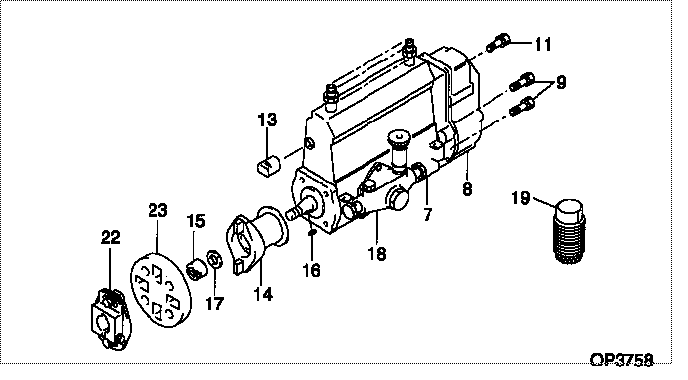
| 000. | [01] | 09000-02151 | PUMP ASSY, INJECTI | 6 064 1107 00 |
| 007. | [01] | 09010-01022 | BODY ASSY, INJECTI | 6 065 1203 01 |
| 008. | [01] | 09080-00630 | GOVERNOR ASSY, MEC | |
| 009. | [04] | 94904-71150 | BOLT, W/WASHER | 6 306 1001 00 |
| 011. | [01] | 91518-08221 | BOLT, W/WASHER | 22815-1190A |
| 013. | [01] | 09001-80220 | COVER, CONTROL RAC | 22114-1050A |
| 014. | [01] | 09255-00060 | BLOCK SUB-ASSY, CO | 6 056 1328 00 |
| 015. | [01] | 09001-20010 | NUT, TIMER ROUND | 22353-1050A |
| 016. | [01] | 94913-00050 | KEY, WOODRUFF | 22891-1040A |
| 017. | [01] | 90258-12001 | WASHER, SPRING | 22873-1310A |
| 018. | [01] | 09210-00212 | PUMP ASSY, FUEL FE | 22570-1200 |
| 019. | [01] | 09006-10011 | COVER, PRIMING PUM | 6 053 1552 60 |
| 022. | [01] | 09240-00043 | COUPLING ASSY | 22610-1090A |
| 023. | [01] | 09243-60020 | COUPLING, INJECTIO | 22612-1020A |
Include in #3:
09000-02151
as PUMP ASSY, INJECTI
Cross reference number
| Part num | Firm num | Firm | Name |
| 09000-02151 | 6 064 1107 | PUMP ASSY, INJECTI |
Information:
Specifications
Structure and Operation
Fuel System (Flow of Fuel)
* The feed pump, which is driven by the driveshaft of the injection pump, draws up the fuel from inside the fuel tank and sends it through the fuel filter, where dust and other impurities in the fuel are filtered out.* The filtered fuel is then sent to the injection pump, where it is pressurized and sprayed out through the injection nozzles into the combustion chamber.* The leak-off fuel from the injection nozzles returns to the fuel tank through the leak-off hose and fuel return pipe.* When the internal fuel pressure of the injection pump exceeds the limit, the overflow valve opens to allow part of the fuel to return to the fuel tank.Fuel Filter
* The fuel filter removes impurities in the fuel through the fuel filter cartridge and also separates water from fuel.* The water that has been separated from the fuel collects at the bottom of the fuel filter. A water separator sensor is installed in the fuel filter, which activates the warning lamp on the meter cluster when the water reaches a certain level.* The water can be drained through the drain port by loosening the drain plug.* A priming pump is provided at the fuel filter head. The priming pump is used for air-bleeding the fuel system.Injection Nozzles
* The injection nozzles are of a throttle type, in which the injection starting pressure is determined by the thickness of the adjusting shim.* When the pressure of the fuel forced into the nozzle by the injection pump (the pressure inside the nozzle tube) presses upon the pressure-receiving surface and overcomes the spring force, the needle valve rises and fuel is sprayed out of the nozzle. * When the pressure acting on the pressure-receiving surface no longer overcomes the force of the spring, the spring pushes the needle valve up and fuel injection is instantly stopped.* Any excess fuel passes through the space between the needle valve and the nozzle to the fuel leak-off pipe, and returns to the fuel tank.Injection Pump
* The injection pump is a compact, lightweight type and has a distribution system that can cope with high revolution operation.* The distribution system is a type that distributes fuel to each cylinder by a single plunger. Fuel to be distributed is filled within the injection pump and lubricates each part in there.Injection pump body
* Drive shaft drives feed pump, cam disc and plunger simultaneously. Plunger spring presses the plunger and the cam disc against roller.* The rotation of cam disc which is driven by drive shaft drives face cam in a rotary movement on roller, creating a reciprocating movement of plunger, which eventually forces the fuel into the cylinder.Governor
* The rotation of drive shaft is transmitted via drive gear to flyweight holder gear to turn flyweight holder.* Flyweight holder is supported by governor shaft. The four flyweights installed in the holder open outward due to the generation of centrifugal force.* The movement of flyweights pushes governor sleeve, and governor