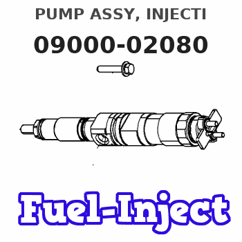
Information pump assy, injecti
Rating:
KIT List:
| Body assy, injecti | 1904400360 |
| Governor assy, mec | 1908900150 |
| Pump assy, fuel fe | 1922900060 |
Components :
| 001. | PUMP ASSY, INJECTI | 09000-02080 |
| 002. | BODY ASSY, INJECTI | 09010-01022 |
| 003. | GOVERNOR ASSY, MEC | 09080-00621 |
| 004. | PUMP ASSY, FUEL FE | 09210-00212 |
| 005. | COUPLING ASSY | 09240-00043 |
Scheme ###:
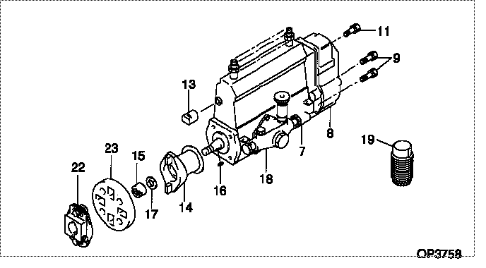
| 000. | [01] | 09000-02080 | PUMP ASSY, INJECTI | 6 064 1102 01 |
| 007. | [01] | 09010-01022 | BODY ASSY, INJECTI | 6 065 1203 01 |
| 008. | [01] | 09080-00621 | GOVERNOR ASSY, MEC | 22330-1150 |
| 009. | [06] | 94900-50191 | SCREW, SLOTTED FLA | 6 056 1305 60 |
| 011. | [01] | 91518-08221 | BOLT, W/WASHER | 22815-1190A |
| 013. | [01] | 09001-80220 | COVER, CONTROL RAC | 22114-1050A |
| 014. | [01] | 09255-00060 | BLOCK SUB-ASSY, CO | 6 056 1328 00 |
| 015. | [01] | 09001-20010 | NUT, TIMER ROUND | 22353-1050A |
| 016. | [01] | 94913-00050 | KEY, WOODRUFF | 22891-1040A |
| 017. | [01] | 90258-12001 | WASHER, SPRING | 22873-1310A |
| 018. | [01] | 09210-00212 | PUMP ASSY, FUEL FE | 22570-1200 |
| 019. | [01] | 09006-10011 | COVER, PRIMING PUM | 6 053 1552 60 |
| 022. | [01] | 09240-00043 | COUPLING ASSY | 22610-1090A |
| 023. | [01] | 09243-60020 | COUPLING, INJECTIO | 22612-1020A |
Include in #3:
09000-02080
as PUMP ASSY, INJECTI
Cross reference number
| Part num | Firm num | Firm | Name |
| 09000-02080 | 6 064 1102 | PUMP ASSY, INJECTI | |
| 6 064 1102 01 | HINO | PUMP ASSY, INJECTI |
Information:
Engine Number, Engine Name Plate
* Serial engine numbers are assigned to the engines in manufacturing sequence. Every engine has its own number. These numbers are required for registration and related inspection of the vehicle. *An engine name plate indicates the following item.* Engine modelHow To Read This Manual
Structure of This Shop Manual
Terminology
Tightening Torques
* Tightening torques are broadly classified as follows:* Bolts and nuts for which tightening torques are specified regardless of installation location are referred to as "standard" bolts and nuts, and their tightening torques are referred to as "standard" tightening torques. (Standard tightening torques are specified in accordance with the sizes and materials of threaded parts.) Identify standard bolts and nuts by comparing them with the following standard tightening torque table. The tightening torques for standard bolts and nuts are shown in this table, and not particularly shown in the text.* The tightening torque for any bolt or nut that is not subject to a standard tightening torque or cannot be identified from the following table is shown in the text.* Any bolt or nut indicated as "wet" must be tightened in a wet condition (with engine oil or grease applied). Any other item must be tightened in a dry condition.Standard tightening torque table
* Use the specified bolts and nuts. Except where otherwise specified, tighten them to the torques shown in the following table.* The threads and seating surfaces must be dry.* If a mating nut and a bolt (or stud bolt) have different strength classifications, tighten to the torque shown for the bolt.(1) Hexagon head bolts and stud bolts (Unit: N m {kgf m} (2) Hexagon head flange bolts (Unit: N m {kgf m} (3) Hexagon nuts (Unit: N m {kgf m} (4) Hexagon flange nuts (Unit: N m {kgf m} (5) Tightening torque for general-purpose flare nut (Unit: N m {kgf m} (6) Tightening torque for general-purpose air piping nylon tube (DIN type) (Unit: N m {kgf m} (7) Tightening torque for general-purpose air piping nylon tube (SAE type) (Unit: N m {kgf m} Units
* Tightening torques and other parameters are given in SI* units with metric units added in brackets { }/ Values in engine specifications, performance curves, and other items taken from official approval documents are given only in metric units. How To Read This Manual
General Work
Part Measurement Methods
* Pay close attention to the following points when measuring parts.Shaft-to-hole clearance measurement, and good/bad evaluation
* Where a shaft-to-hole clearance is specified as a service standard, measurement and good/bad evaluation must be performed as follows:* Choose at least two measurement locations along the length of the shaft. Add measurement locations depending on the length of the shaft. The following example assumes three measurement locations.* At each measurement location (a, b, and c), measure the shaft diameter and hole diameter in two directions perpendicular to each other. Note the smaller shaft measurement (min) and larger hole measurement (max) at each measurement location.Shaft: da min, db min, dc minHole: Da max, Db max, Dc max* For each