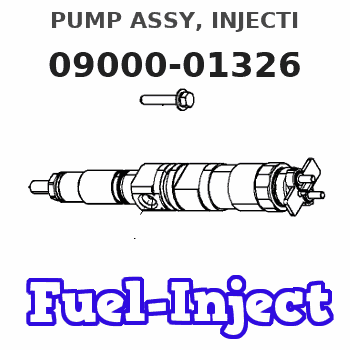
Information pump assy, injecti
Rating:
Components :
| 001. | PUMP ASSY, INJECTI | 09000-01326 |
| 002. | BODY ASSY, INJECTI | 09010-00785 |
| 003. | TIMER ASSY, AUTOMA | 09180-00192 |
| 004. | PUMP ASSY, FUEL FE | 09210-00372 |
Scheme ###:
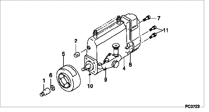
| 000. | [01] | 09000-01326 | PUMP ASSY, INJECTI | 30861-10014 |
| 001. | [01] | 09001-20260 | NUT, TIMER ROUND | ME703450 |
| 002. | [01] | 09001-80061 | COVER, CONTROL RAC | ME728161 |
| 004. | [01] | 09010-00785 | BODY ASSY, INJECTI | ME020838 |
| 005. | [01] | 09180-00192 | TIMER ASSY, AUTOMA | ME021954 |
| 006. | [01] | 94901-50500 | WASHER, SPRING | ME008373 |
| 007. | [01] | 91518-08221 | BOLT, W/WASHER | MM500963 |
| 008. | [01] | 09080-00395 | GOVERNOR ASSY, MEC | ME021091 |
| 009. | [01] | 09210-00372 | PUMP ASSY, FUEL FE | ME02082701 |
| 010. | [01] | 94913-00160 | KEY, WOODRUFF | ME022425 |
| 011. | [06] | 94900-50191 | SCREW, SLOTTED FLA | ME022439 |
Include in #3:
09000-01326
as PUMP ASSY, INJECTI
Cross reference number
| Part num | Firm num | Firm | Name |
| 09000-01326 | 30861-1001 | PUMP ASSY, INJECTI |
Information:
Removal
Invert engine.
Fig. 1-Engine InvertedRemove oil pan (1, Fig. 1) (Group 0407).Remove engine timing gear cover (2) (Group 0402).Remove flywheel and flywheel housing (Group 0433).Crankshaft End Play
Fig. 2-Crankshaft End PlayPosition a dial indicator against end of crankshaft (Fig. 2). IMPORTANT: Do not apply too much pressure with pry bar as this could damage bearings.Using pry bar, carefully move crankshaft rearward.Zero the dial indicator.Using pry bar, carefully move crankshaft forward.Read dial indicator.
Fig. 3-Crankshaft End PlaySpecifications are as follows: New crankshaft end play ... 0.002 to 0.008 inch(0.05 to 0.20 mm)Maximum crankshaft end play ... 0.015 inch(0.38 mm)
Fig. 4-Main Bearing Cap PositionsRemove connecting rod caps (Fig. 4). Push pistons and connecting rods toward the cylinder head.Check main bearing caps for identifying numbers. If there are no numbers, stamp corresponding numbers in one oil pan rail and in main bearing cap. Stamp the number in each main bearing cap off center to the same side as the number in the oil pan rail. This will assure correct indexing of main bearing caps during installation.Remove main bearing caps.Lift crankshaft from cylinder block.Remove main bearing inserts from cylinder block and from main bearing caps.Repair
Measure crankshaft main journal to main bearing clearance.
Fig. 5-Main Bearing ClearanceMain bearing journal O.D. (new) (1, Fig. 5) ... 3.123 to 3.124 inch(79.32 to 79.35 mm)Assembled Main bearing I.D. (new) (2) ... 3.126 to 3.128 inch(79.39 to 79.45 mm)Main bearing clearance (new) (3) ... 0.0016 to 0.0046 inch(0.041 to 0.117 mm)Main bearing clearance (maximum) ... 0.006 inch(0.15 mm)Main bearing bore I.D. (4) ... 3.325 to 3.326 inch(84.46 to 84.48 mm)Measure crankshaft main journal taper and roundness.
Fig. 6-Main Bearing MeasurementJournal taper (maximum) (1, Fig. 6) ... 0.001 inch per 1.00 inch(0.03 mm per 25.4 mm)Journal out-of-round (maximum) (2, Fig. 6) ... 0.003 inch(0.08 mm)If wear is even, but out of specifications, dress crankshaft main journals and select proper undersize bearing inserts.If journals are out-of-round or tapered, grind crankshaft and select proper undersize bearing inserts.If crankshaft end play is excessive, replace worn thrust bearings or grind crankshaft thrust surfaces and select proper oversize thrust bearing.Installation
Fig. 7-Main Bearing Insert InstallationPosition bearing inserts in cylinder block and main bearing caps with the tang on the insert engaged in the slot in the cylinder block and main bearing caps (Fig. 7).Apply a coat of clean engine oil to the bearing surface of the inserts.Position crankshaft in cylinder block. Tangs on main bearing halves in main bearing caps must be positioned to the same side of the crankshaft as the tangs on main bearing halves in cylinder block.
Fig. 8-Main Bearing Cap PositionsInstall main bearing caps with numbers (1, Fig. 8) corresponding to numbers in oil pan rail (2). If there is no arrow (3) machined on main bearing cap, install cap with number to same side as numbers in oil pan rail. If there is an arrow machined on main bearing cap, arrow must point toward camshaft side.Dip main bearing cap screws in clean engine oil and position them in the main