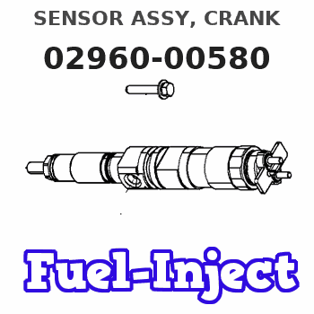
Information sensor assy, crank
Rating:
Compare Prices: .
As an associate, we earn commssions on qualifying purchases through the links below

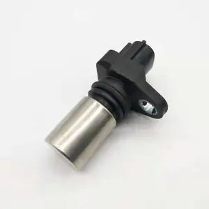
Engine Speed Sensor Revolution Crankshaft Camshaft Position 6217-81-9210 029600-0580 Compatible with PC400-7 PC450-8 PC200-5 Excavator Parts Machinery Parts (A)
Generic Engine Speed Sensor Revolution Crankshaft Camshaft Position 6217-81-9210 029600-0580 Compatible with PC400-7 PC450-8 PC200-5 Excavator Parts Machinery Parts || Place of Origin:Guangdong, China
Generic Engine Speed Sensor Revolution Crankshaft Camshaft Position 6217-81-9210 029600-0580 Compatible with PC400-7 PC450-8 PC200-5 Excavator Parts Machinery Parts || Place of Origin:Guangdong, China

Engine Speed Sensor Applicable for 90919-05053 029600-0580
Generic Function: The vehicle speed sensor is made of ABS material to detect engine speed, ensure stable operation, and can be used for a long time. || Material: The sensor is made of high-quality plastic, which is durable, not easy to fade, and wear-resistant, ensuring maximum strength and durability for long-term use. || Easy to use: This vehicle speed sensor is easy to install, plug and play, and can be replaced without other complicated tools. || Features: Detect engine speed, piston end position, and ignition cylinder end signal to ensure performance and fuel efficiency. || Please check your vehicle model, year, and part number carefully to ensure that the parts are compatible. If you have any questions, please contact us directly through Amazon message.
Generic Function: The vehicle speed sensor is made of ABS material to detect engine speed, ensure stable operation, and can be used for a long time. || Material: The sensor is made of high-quality plastic, which is durable, not easy to fade, and wear-resistant, ensuring maximum strength and durability for long-term use. || Easy to use: This vehicle speed sensor is easy to install, plug and play, and can be replaced without other complicated tools. || Features: Detect engine speed, piston end position, and ignition cylinder end signal to ensure performance and fuel efficiency. || Please check your vehicle model, year, and part number carefully to ensure that the parts are compatible. If you have any questions, please contact us directly through Amazon message.

You can express buy:
USD 11.9
13-05-2025
13-05-2025
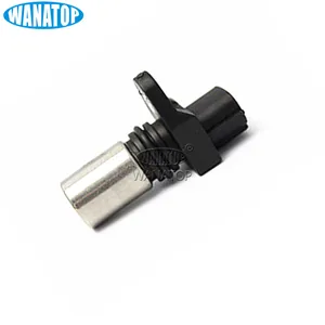
1pc 029600-0580 029600 0580 high quality Crankshaft Position Sensor For ISUZU- KOMATSU- 0296000580 PC450-7 fast delivery
USD 20.91
19-05-2025
19-05-2025
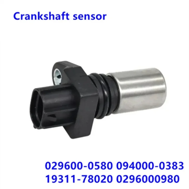
OEM 029600-0580 094000-0383 23731-8H800 6235614 19311-78020 0296000980 S894111310 8971905100 5894111310 Engine Crankshaft sensor
USD 22
13-05-2025
13-05-2025
Crankshaft Position Sensor 029600-0580 029600 0580 0296000580 PC450-7 For Hino J08C J05C
Images:
USD 17.11

[19-May-2025]
USD 20.97

[13-May-2025]
USD 25

[21-Apr-2019]
USD 28

[23-Aug-2022]
Include in #3:
Cross reference number
| Part num | Firm num | Firm | Name |
| 02960-00580 | 89411-1290 | SENSOR ASSY, CRANK | |
| 8-97174899-0 | ISUZU | SENSOR ASSY, CRANK | |
| 89411-1290A1 | HINO | SENSOR ASSY, CRANK | |
| 89411-1290A | HINO | SENSOR ASSY, CRANK | |
| 89411-1290 | HINO | SENSOR ASSY, CRANK |
Information:
Problem
The fuel lines on certain D10N Tractors; 651E And 657E Tractors; 772B Tractors; 773B Trucks; and 992C Loaders may fail. New fuel line groups can be installed that have a longer service life.
Affected Product
Model & Identification Number
Group 1
D10N (2YD442-1937, 2YD1939, 2YD1942)
651E (89Z170-172, 89Z174-187, 89Z189-270)
657E (90Z183-206; 91Z310-434)
772B (64W178-183)
773B (63W2172, 63W2173, 63W2175, 63W2177-3417, 63W3419; 5SC1-140)
992C (49Z1120-1878)
Group 2
D10N (2YD1938, 2YD1940-1941, 2YD1943-2230)
657E (90Z207-208; 91Z435-460)
772B (64W184-208)
773B (63W3418, 63W3420-3686)
992C (49Z1879-2015)
Group 3
D10N (2YD2231-2406)
657E (90Z209-220)
773B (63W3687-3940)
992C (49Z2016-2125)
Parts Needed
Group 1
1 - 7C6589 Clamp 2 - 7C6591 Clamp 2 - 7C7747 Clamp 1 - 7E3539 Lines Group 1 - 6I0347 Bracket Assembly 1 - 6I0361 Lines Group 6 - 9N3388 Screw-Lock2 - 4P3677 Clamp2 - 4P3678 Clamp8 - 5P4939 Screw A2 - 0L2070 Bolt5 - 0S1590 Bolt3 - 8T1296 Washer2 - 9Y3357 Clamp2 - 688438 Spacer1 - 1029228 Clamp AssemblyGroup 2
1 - 6I0347 Bracket2 - 7C6591 Clamp2 - 7C7747 Clamp2 - 4B4274 Washer2 - 9N3388 Screw1 - 6I4813 Clamp Kit1 - 8T1296 Washer2 - 5P4939 Screw1 - 9Y3357 Clamp1 - 1029228 Clamp AssemblyGroup 3
2 - 5P4939 Screw1 - 9Y3357 Clamp1 - 1029228 Clamp AssemblyAction Required
See the attached procedure.
Service Claim Allowances
Group 1 Affected Product
All Group 2 Affected Product
This is a 1-hour job.
All Group 3 Affected Product
This is a .3-hour job. Submit a supplemental claim for Group 3 if a claim for Group 1 or 2 has already been submitted.
Parts Disposition
Handle the parts in accordance with your Warranty Bulletin on warranty parts handling.
Attach. (1-Rework Procedure)Rework Procedure
Refer to the following instructions and illustrations. Replace the existing fuel lines and their related parts with the new fuel line groups.
To insure correct clamp locations, install left and right fuel line groups as assembled. However, if clamps are removed, mark locations to insure correct positions when reassembling.
On the 992C Wheel Loader, it is necessary to remove the 6N8322 Air Outlet Tube Assembly to be able to install the right bank fuel line group.
Tighten the fuel line clamp screws to a torque of 2.25 N m (20 lb in). Do not over tighten. Use a 6V6069 Torque Screwdriver or similar tool to tighten the screws.
Group 1 Procedure
1. Clean and paint the new 6I0361 and 7E3539 Fuel Line Groups before proceeding to the job site.A) "Tape Off" the number 3, 5, and 6 fuel lines in the area of the tower clamp. (See Illustration 1 - Part 4 of 5, Section C-C)B) Install 5F2807 Plastic Caps and 2F2990 Plastic Plugs on the ends of the fuel lines.C) Clean and paint the fuel line groups.D) After drying completely, remove the tape. Do not remove the plastic caps and plugs until the fuel lines are ready to be installed on the engine. Transport the fuel line groups in their original boxes.2. Remove all mounting bolts from the fuel line brackets at the aftercooler housing. Except for the tower clamp assembly, new mounting bolts and washers will be used. Keep the washers. The washers may be needed later as spacers.3. A) Disassemble the tower clamp assembly behind the fuel injection pump. The 9Y3356 Clamp and 9Y3359