Information delivery-valve assembly
BOSCH
9 413 610 462
9413610462
ZEXEL
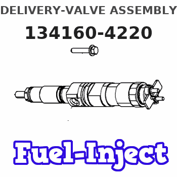
134160-4220
1341604220
ISUZU
1156410400
1156410400
Rating:
Include in ###:
Cross reference number
Zexel num
Bosch num
Firm num
Name
134160-4220
9 413 610 462
1156410400 ISUZU
DELIVERY-VALVE ASSEMBLY
C 14FD DELIVERY VALVE DV(P,PD) DV
C 14FD DELIVERY VALVE DV(P,PD) DV
Information:
Illustration 9 g06426461
(1) For 323, 330, and 330GC machines use 580-1893 Plate As / For 336GC machines use 581-5268 Plate As
(Q) Bolt and washer
(R) Plate
Install plate assembly (1) using plate (R), bolt, and washer (Q). Tighten the bolts to 55 10 N m (41 7 lb ft). Refer to Illustration 9.
Illustration 10 g06426462
(7) 365-0162 Special Connector
(F) Injector
Install special connector (7) to injector (F). Refer to Illustration 10.
Illustration 11 g06426463
(2) 573-8722 Tank
(8) 3S-2093 Cable Strap
(E) Hose
(M) Harness
Connect hose (E) to tank (2). Refer to Illustration 11.
Illustration 12 g06426465
View of area T
(1) For 323, 330, and 330GC machines use 580-1893 Plate As / For 336GC machines use 581-5268 Plate As
(P) Clip
(S) Bolt and washer
(D1) 45 Degree
Install clip (P) using bolt and washer (S), torque to 28 7 N m (248 62 lb in). Refer to Illustration 12.
Secure the harness (M) using cable strap (8). After tie up, cut all the surplus of strap. Refer to Illustration 11.
Reinstall upper cover (A) and close the upper cover (B). Refer to Illustration 1 and Illustration 2.Replacement Procedure for 336 Excavators
Do not operate or work on this product unless you have read and understood the instruction and warnings in the relevant Operation and Maintenance Manuals and relevant service literature. Failure to follow the instructions or heed the warnings could result in injury or death. Proper care is your responsibility.
Table 3
Required Parts
Item Qty Part Number Part Name
1 1 471-9926 Tank
2 1 581-3324 Plate As
3 1 327-0325 Cable Strap
Illustration 13 g06426466
(A) Upper cover
(B) Upper cover
Remove the upper cover (A) and open the upper cover (B). Refer to Illustration 13.
Illustration 14 g06426467
(C) Tank assembly
(E) Hose
(F) Hose
(G) Strap
Disconnect hose (E) and hose (F) from tank assembly (C). Cut and remove the strap (G). Refer to Illustration 14.
Illustration 15 g06426468
(C) Tank assembly
(H) Bolt and washer
(J) Bolt and washer
(K) Plate assembly
Remove tank assembly (C) by loosening the bolt and washer (H). Refer to Illustration 15.
Remove plate assembly (K) by loosening the bolt and washer (J). Refer to Illustration 15.
Illustration 16 g06426469
(F) Hose
(D1) 10.0 mm (0.4 inch)
Cut and remove the end of hose (F) by 10.0 mm (0.4 inch). Refer to Illustration 16.
Illustration 17 g06426470
(1) 471-9926 Tank
(2) 581-3324 Plate As
(3) 327-0325 Cable Strap
(E) Hose
(H) Bolt and washer
(J) Bolt and washer
(F) Hose
Install the plate assembly (2) and tank (1) using bolt and washer (J) and bolt and washer (H). Refer to Illustration 17.
Connect hose (E) and hose (F) to tank (1). Add cable strap (3) to secure hose. After tie up, cut all the surplus of strap. Refer to Illustration 17.
Reinstall upper cover (A) and close the upper cover (B). Refer to Illustration 13.
Have questions with 134160-4220?
Group cross 134160-4220 ZEXEL
Isuzu
134160-4220
9 413 610 462
1156410400
DELIVERY-VALVE ASSEMBLY