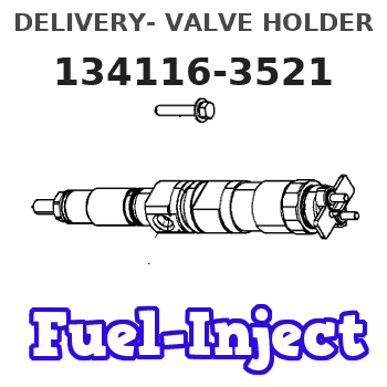
Information delivery- valve holder
BOSCH
9 411 610 723
9411610723
ZEXEL
134116-3521
1341163521
HINO
221081180A
221081180a

Rating:
Include in ###:
Cross reference number
Zexel num
Bosch num
Firm num
Name
134116-3521
9 411 610 723
221081180A HINO
DELIVERY- VALVE HOLDER
C 14FR HOLDER;D.V. parts(P,PD) Others
C 14FR HOLDER;D.V. parts(P,PD) Others
134116-3521
9 411 610 723
221081190A HINO
DELIVERY- VALVE HOLDER
A C 14FR HOLDER;D.V. parts(P,PD) Others
A C 14FR HOLDER;D.V. parts(P,PD) Others
Information:
1. Remove two bolts (1) from the top of the water pump. Loosen two bolts (2) in the water pump.
TYPICAL EXAMPLE2. Remove oil supply line (3) from the turbocharger. Remove oil return line (4) from the turbocharger.
TYPICAL EXAMPLE3. Remove the bolts (5) that hold the cylinder head to the cylinder block.
TYPICAL EXAMPLE4. Fasten a hoist to the cylinder head assembly (6). Remove the cylinder head assembly from the block. Weight of the assembly is 290 lb. (131 kg). Remove O-ring seal from hollow dowel. Remove cylinder head gasket (7) and water ferrules.
Do not put the cylinder head down on a flat surface. This can cause damage to the fuel injection valves.
Always install a new gasket between spacer plate and cylinder block before cylinder head is installed. See REMOVE SPACER PLATE.Install Cylinder Head
TYPICAL EXAMPLE1. Thoroughly clean the spacer plate and bottom surface of the cylinder head. Install a new head gasket (2), water ferrules (1) and O-ring seal (3) on the hollow dowel. Be sure a new gasket has been installed between spacer plate and cylinder block. See INSTALL SPACER PLATE.2. Fasten a hoist and install the cylinder head assembly (4) on the cylinder block. 3. Install the push rods and put the rocker shaft in position on the cylinder head. Put 5P3931 Anti-Seize Compound on the threads of the cylinder head and rocker shaft bolts. Install the bolts and washers and tighten the bolts as follows: 1. Tighten all bolts in number sequence to a torque of 115 lb. ft. (155 N m).2. Again tighten all bolts in number sequence to a torque of 185 13 lb. ft. (250 17 N m).3. Again tighten all bolts in number sequence (hand torque only) to a torque of 185 13 lb. ft. (250 17 N m).4. Tighten all bolts in letter sequence to a torque of 32 5 lb. ft. (43 7 N m).4. Make adjustment of valves to have a clearance of .015 in. (0.38 mm) for intake and .025 in. (0.64 mm) for exhaust.
TYPICAL EXAMPLE5. Install oil return line (6) on the turbocharger.6. Install oil supply line (5) on the turbocharger. 7. Tighten the two bolts (8) in the water pump.8. Install the two bolts (7) that hold the water pump to the cylinder head.end by: a) install fuel injection lines
Have questions with 134116-3521?
Group cross 134116-3521 ZEXEL
Hino
134116-3521
9 411 610 723
221081180A
DELIVERY- VALVE HOLDER
134116-3521
9 411 610 723
221081190A
DELIVERY- VALVE HOLDER
