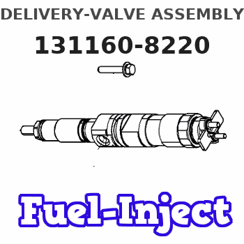
Information delivery-valve assembly
BOSCH
9 413 610 442
9413610442
ZEXEL
131160-8220
1311608220
ISUZU
8971676700
8971676700
Rating:
Compare Prices: .
As an associate, we earn commssions on qualifying purchases through the links below

$61.82
04 Mar 2024
CN: Diesel Injection Par
Cabezales 6Pcs Diesel Pump Fuel Plunger Barrel Assembly 134151-3220 9413610442 P112 Fit for NISSAN DIESEL Big Thumb PD6 PF6 PE6 PE6T PF6T PF6TC
Cabezales Manufacturer MFR Number:134151-3220,1679599018,9 413 610 442,9413610442 Stamping No.: P112 || Package: 6 pieces of plunger and barrel.Neutral packing. || Application:Fit for NISSAN DIESEL Big Thumb PD6 PF6 PE6 PE6T PF6T PF6TC. || Premium Quality:Our plungers and barrels made of premium strength metal and composite plastic.we have a good air and fuel mixing ability and excellent ability of fuel pump systems,and plunger assembly be inspected reliability and durability in the factory. || Notice:Please you carefully check your vehicle plunger barrel and make sure that the number must be completely the same as our description fitment,if you have any problem,please you contact us by email,we will have professional customer service within 24 hours.
Cabezales Manufacturer MFR Number:134151-3220,1679599018,9 413 610 442,9413610442 Stamping No.: P112 || Package: 6 pieces of plunger and barrel.Neutral packing. || Application:Fit for NISSAN DIESEL Big Thumb PD6 PF6 PE6 PE6T PF6T PF6TC. || Premium Quality:Our plungers and barrels made of premium strength metal and composite plastic.we have a good air and fuel mixing ability and excellent ability of fuel pump systems,and plunger assembly be inspected reliability and durability in the factory. || Notice:Please you carefully check your vehicle plunger barrel and make sure that the number must be completely the same as our description fitment,if you have any problem,please you contact us by email,we will have professional customer service within 24 hours.
Include in ###:
Cross reference number
Zexel num
Bosch num
Firm num
Name
131160-8220
9 413 610 442
8971676700 ISUZU
DELIVERY-VALVE ASSEMBLY
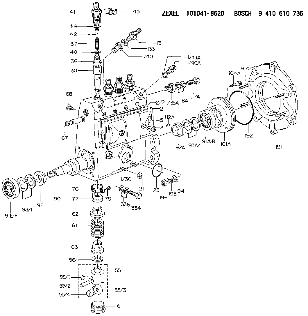
C 14EX DELIVERY VALVE DV(A) DV
C 14EX DELIVERY VALVE DV(A) DV
131160-8220
9 413 610 442
221030524A HINO
DELIVERY-VALVE ASSEMBLY
C 14EX DELIVERY VALVE DV(A) DV
C 14EX DELIVERY VALVE DV(A) DV
Information:
Start By:a. remove oil pump1. Check the identification marks on the connecting rods and caps as to their location in the engine. The caps must be installed in original positions in the engine.2. Turn the crankshaft until two of the pistons are at bottom center. 3. Remove connecting rod caps (1) from the connecting rods. Remove the lower half of the bearings from the caps.
Be careful not to damage the crankshaft journals. Do not turn the crankshaft while any of the connecting rod caps are removed.
4. Push the connecting rod away from the crankshaft, and remove the upper half of the bearings from the connecting rods.5. Make sure the surface of the connecting rod where the bearings make contact is clean and free of dirt.
Make sure the tabs on the bearings are in alignment with the notches in the connecting rods and caps.
6. Install the upper half of new bearings in the connecting rods.7. Pull the connecting rod down slowly on the crankshaft.
Make sure the surfaces where the bearings make contact in the caps are clean and free of dirt.
8. Install new bearings (2) in the caps. Make sure the tabs on the bearings are in alignment with the notches in the caps.The serviceman must be very careful to use Plastigage correctly. The following points must be remembered:... Make sure that the backs of the bearings and the bores are clean and dry.... Make sure that the bearing locking tabs are properly seated in their slots.... The crankshaft must be free of oil where the Plastigage touches it.... Put a piece of Plastigage on the crown of the bearing half that is in the cap. Do not allow the Plastigage to extend over the edge of the bearing.... Install the bearing cap using the correct torque-turn specifications. Do not use an impact wrench. Be careful not to dislodge the bearing when the cap is installed.... Do not turn the crankshaft with the Plastigage installed. ... Carefully remove the cap but do not remove the Plastigage. Measure the width of the Plastigage while it is in the bearing cap or on the crankshaft journal. Do this by using the correct scale on the package. Record the measurements.... Remove the Plastigage before installing the cap.When using Plastigage, the readings can sometimes be unclear. For example, all parts of the Plastigage are not the same width. Measure the major widths to make sure that they are within the specification range. Also, experience has shown that when checking clearances tighter than 0.10 mm (.004 in) the readings may be low by 0.013 to 0.025 mm (.0005 to .0010 in). Out-of-round journals can give faulty readings. Also, journal taper may be indicated when one end of the Plastigage is wider that the other.For complete details concerning measuring bearing clearances, see Engine Bearings & Crankshafts, SEBD0531.9. Put 2P-2506 Thread Lubricant on the threads of the bolts in the connecting rods.10. Check the bearing clearance with Plastigage (A) as follows:
When Plastigage is used to check
Have questions with 131160-8220?
Group cross 131160-8220 ZEXEL
Isuzu
131160-8220
9 413 610 442
8971676700
DELIVERY-VALVE ASSEMBLY
Hino
131160-8220
9 413 610 442
221030524A
DELIVERY-VALVE ASSEMBLY