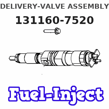
Information delivery-valve assembly
BOSCH
9 413 610 440
9413610440
ZEXEL
131160-7520
1311607520
ISUZU
8971236050
8971236050

Rating:
Compare Prices: .
As an associate, we earn commssions on qualifying purchases through the links below
Include in ###:
Number on scheme 36


1010404030
as DELIVERY-VALVE ASSEMBLY
1010404170
as DELIVERY-VALVE ASSEMBLY
57A
1010418290
as DELIVERY-VALVE ASSEMBLY
1010418430
as DELIVERY-VALVE ASSEMBLY
57A
1010418650
as DELIVERY-VALVE ASSEMBLY
Cross reference number
Zexel num
Bosch num
Firm num
Name
131160-7520
8971236050 ISUZU
DELIVERY-VALVE ASSEMBLY
C 14EX DELIVERY VALVE DV(A) DV
C 14EX DELIVERY VALVE DV(A) DV
Information:
There are two water temperature regulators, one for each cylinder head.1. Drain the coolant from the engine to a level below the water temperature regulators.
Typical Example2. Remove elbow (1). Remove tube and elbow (2). 3. Remove cover assemblies (3). 4. Remove water temperature regulator (4) from each cover assembly. 5. Remove lip-type seal (5) from each cover assembly if a replacement is necessary.6. Check the water temperature regulators. See Specifications Manual SENR6475. The following steps are for the installation of the water temperature regulators. 7. Use Tool (A) to install lip-type seals (5). Install the seals with the lip toward the inside of the covers. Install the seal until it contacts the counterbore in the cover assembly.
If the water temperature regulators are installed incorrectly the engine will over heat.
8. Put clean glycerin on the lip of seal (5), and install water temperature regulator (4) in each cover assembly (3). 9. Install new gaskets (6) and cover assemblies (3).
Typical Example10. Install the gaskets and elbow (1). Put clean engine oil or glycerin on the O-ring seals on tube (2). Install the gasket, tube and elbow (2).11. Fill the cooling system to the correct level. See the Operation & Maintenance Manual.
