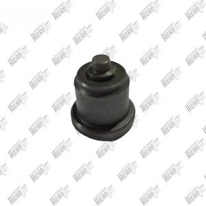
Information delivery-valve assembly
BOSCH
9 413 610 033
9413610033
ZEXEL
131110-7920
1311107920
HINO
221031330A
221031330a

Rating:
Compare Prices: .
As an associate, we earn commssions on qualifying purchases through the links below

$21.73
29 Aug 2019
Bosch: Bosch
Bosch 9413610033 Delivery-Valve Assembly
You can express buy:
USD 53.62
17-05-2025
17-05-2025
For Fuel Injection Pump Delivery Valve A60 9413610033 D Valve 1311107920 131110-7920 9 413 610 033 Excavator
Include in ###:
Cross reference number
Information:
Removal
Disconnect battery negative (-) cable at the battery terminal.Allow engine to cool.Drain cooling system.Remove alternator, fan belts, fan and sheet metal fan pulley.
Fig. 1-Bypass HoseDisconnect cooling system bypass hose (Fig. 1) at top of water pump.Disconnect lower radiator hose at water pump and engine oil cooler hose at lower rear of water pump (1, Fig. 2).
Fig. 2-Water Pump RemovalRemove water pump attaching hardware (2, Fig. 2) and remove water pump from engine.Disassembly
Fig. 3-Cover Plate RemovalRemove cover plate cap screws (1, Fig. 3). Lift cover plate (2) and gasket (3) off water pump.3-164D, 3-179D, 4-219D, 4-239D, 4-276D, or 6-329D Engine
Fig. 4-D01200AA PullerUsing D01200AA Puller (Fig. 4), remove pulley or pulley hub.
Fig. 5-JD262A Bearing DriverSupport housing from impeller end. Using JD262A Bearing Driver (Fig. 5), push bearing and impeller out of housing from pulley end.
Fig. 6-0.5 in. (13 mm) DriftSupport impeller from bearing side. Using a 0.5 in. (13 mm) drift (Fig. 6), push bearing shaft out of impeller.Lift seal off bearing shaft.4-239T, 4-276T, 6-359D, 6-359T, 6-414D, or 6-414T Engine
Fig. 7-D01200AA PullerUsing D01200AA Puller, remove pulley. IMPORTANT: Do not attempt to push shaft from pulley end. A flange in the bearing bore prevents bearing passage through housing.
Fig. 8-D01200AA PullerUsing D01200AA Puller, remove impeller.
Fig. 9-Bearing ShaftSupport pulley end of housing. Select a 0.5 in. (13 mm) diameter by 3.0 in. (76 mm) drift. Push against impeller end of bearing shaft (Fig. 9) to push bearing out of housing. IMPORTANT: Always replace a bearing that has been removed from pump.Repair
Fig. 10-Seal and InsertsInspect seal (2, Fig. 10) and ceramic insert (1) for damage. The lapped surfaces can not be grooved, chipped, cracked, or scratched.If there are traces of coolant on bearing or if there was leakage from drain hole in bottom of housing, the seal is leaking.To remove metal type seal, use a punch to drive it out of the housing from the bearing side.To remove rubber type seal, peel it out of the housing from the impeller side.If seal is replaced, also remove ceramic insert and cupped rubber insert from counterbore in impeller.Inspect housing for damage behind impeller. Replace housing and impeller if metal has been scrapped away. IMPORTANT: Always replace bearing that has been removed from pump.Assembly
IMPORTANT: Do not push against end of bearing shaft. Push against outer race only.
Fig. 11-JD262A or JDE74 Bearing DriverFor water pumps on engines 3-164D, 3-179D, 4-219D, 4-239D, 4-276D and 6-329D, use JD262A Bearing Driver (Fig. 11).For water pumps on engines 4-239T, 4-276T, 6-359D, 6-359T, 6-414D and 6-414T, use JDE74 Bearing Driver (Fig. 11).Push bearing into housing until outer end of bearing is flush with the housing. IMPORTANT: Do not touch lapped surface of seal.
Fig. 12-SealSparingly coat the flange portion of the seal with joint sealing compound. Press seal into housing by hand until flange bottoms on housing (Fig. 12). Wipe away any excess joint sealing compound.
Fig. 13-InsertsPlace ceramic insert in cupped rubber insert with "V" groove on ceramic insert toward cupped rubber insert. Be sure parts are dry and clean.Dip inserts in light oil