Information cover
BOSCH
9 421 615 665
9421615665
ZEXEL
159228-0120
1592280120
ISUZU
8943369300
8943369300
Rating:
Include in ###:
Cross reference number
Zexel num
Bosch num
Firm num
Name
159228-0120
9 421 615 665
8943369300 ISUZU
COVER
C 14GJ COVER GOV
C 14GJ COVER GOV
Information:
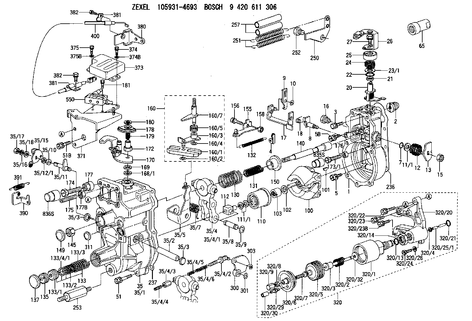
1. Remove wiring harnesses from bracket (1). 2. Disconnect the wires at connections (5) Remove line (4). Remove five bolts (2), bracket (1) cover (3) and the gasket. 3. Remove two bolts (6) and clamps. Remove rack solenoid. (7) 4. Disconnect wires at connections (8). Remove two bolts (10) and bracket assembly (9). Loosen the locknut and remove rack position sensor (11). Be careful not to lose the spring that is around the sensor. To remove the transducer module at this time use the following procedure.a. disconnect wires at connector (8)b. remove the connector from the wiresc. remove four bolts that fasten transducer module (22) to housing (15)d. feed the wires through housing (18) while removing the transducer module. 5. Remove three bolts (12) from inside housing (14). Remove two bolts (13) and remove housing (14). 6. Loosen locknut (15) and remove engine speed sensor (16). 7. Remove seven bolts (17) and remove the transducer module and housing (18). 8. Remove three bolts (19) and cover (20). 9. Remove two bolts (21). Remove transducer module (22) and gasket. 10. Remove lockring (27), seat (25), spring (24), sleeve (23) and lockring (26). 11. Remove three bolts (28) and remove cylinder (29). 12. Remove sleeve (30), piston (31) and valve (32). Remove O-ring seal (33) from sleeve (30). 13. Remove bolts (34) and remove retainer (35). Remove two races and one bearing (not shown).Assemble Rack Actuator Package
1. Lubricate bearing (37) with engine oil. Install race (36), bearing (37), race (36) and retainer (35) on the fuel injection pump camshaft. 2. Lubricate O-ring seal (33) with engine oil and install on sleeve (30). Install sleeve (32) and piston (31) into sleeve (33). 3. Install sleeve (30) into cylinder (29).4. Install lockring (26), sleeve (23), spring (24), seat (25) and lockring (27) on valve (32). 5. Put cylinder assembly (29) in position on the fuel injection pump housing with piston (31) engaged over fuel injection pump rack (38). Be sure that rack (38) is properly engaged with piston (31). 6. Fasten cylinder (29) to the fuel injection pump housing with three bolts (28). The rack and servo valve (32) must move freely after bolts (28) are tight. 7. Install gasket (39) and transducer module (22) on housing (18). 8. Place wire harness (40) in the slot of the housing. 9. Install cover (20) and bolts (19). 10. Install the gasket and housing (18) on the fuel injection pump housing with seven bolts (17). 11. Install engine speed sensor (16) until it contacts retainer (35). Back the engine speed sensor out (counterclockwise) 180°. This procedure will provide a clearance of .76 mm (.030 in). Tighten locknut (15) to a torque of 13 2 N m (10 1 lb.ft.). 12. Install gasket and housing (14).13. Install the rack position sensor damping seal in housing (14). Install the spring and rack position sensor (11) in housing (14). 14. Connect the rack position sensor wiring connector to the transducer module wiring connector (P8 to
1. Lubricate bearing (37) with engine oil. Install race (36), bearing (37), race (36) and retainer (35) on the fuel injection pump camshaft. 2. Lubricate O-ring seal (33) with engine oil and install on sleeve (30). Install sleeve (32) and piston (31) into sleeve (33). 3. Install sleeve (30) into cylinder (29).4. Install lockring (26), sleeve (23), spring (24), seat (25) and lockring (27) on valve (32). 5. Put cylinder assembly (29) in position on the fuel injection pump housing with piston (31) engaged over fuel injection pump rack (38). Be sure that rack (38) is properly engaged with piston (31). 6. Fasten cylinder (29) to the fuel injection pump housing with three bolts (28). The rack and servo valve (32) must move freely after bolts (28) are tight. 7. Install gasket (39) and transducer module (22) on housing (18). 8. Place wire harness (40) in the slot of the housing. 9. Install cover (20) and bolts (19). 10. Install the gasket and housing (18) on the fuel injection pump housing with seven bolts (17). 11. Install engine speed sensor (16) until it contacts retainer (35). Back the engine speed sensor out (counterclockwise) 180°. This procedure will provide a clearance of .76 mm (.030 in). Tighten locknut (15) to a torque of 13 2 N m (10 1 lb.ft.). 12. Install gasket and housing (14).13. Install the rack position sensor damping seal in housing (14). Install the spring and rack position sensor (11) in housing (14). 14. Connect the rack position sensor wiring connector to the transducer module wiring connector (P8 to
Have questions with 159228-0120?
Group cross 159228-0120 ZEXEL
Isuzu
159228-0120
9 421 615 665
8943369300
COVER