Information coupling plate
BOSCH
9 423 618 548
9423618548
ZEXEL
156643-7521
1566437521
ISUZU
8973676250
8973676250
Rating:
Scheme ###:
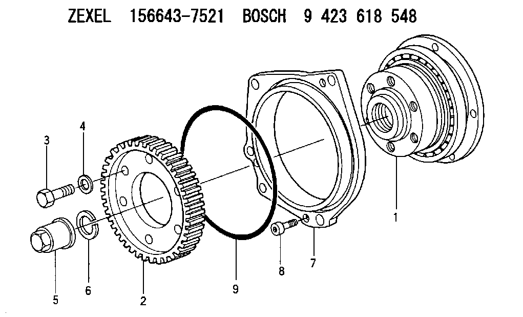
| 1. | [1] | 156643-7121 | COUPLING PLATE |
| 2. | [1] | 156221-9900 | TOOTHED GEAR |
| 3. | [6] | 156634-5200 | BLEEDER SCREW |
| 4. | [6] | 156615-6601 | PLAIN WASHER |
| 5. | [1] | 156809-0100 | UNION NUT |
| 6. | [1] | 156809-0000 | LOCKING WASHER |
| 7. | [1] | 156642-1002 | COVER |
| 8. | [3] | 010206-1640 | HEX-SOCKET-HEAD CAP SCREW M6P1L16 |
| 9. | [1] | 156642-0500 | O-RING |
Include in #1:
107492-1084
as COUPLING PLATE
Cross reference number
Zexel num
Bosch num
Firm num
Name
156643-7521
9 423 618 548
8973676250 ISUZU
COUPLING PLATE
K 14GU COUPLING COUP
K 14GU COUPLING COUP
Information:
1. Disconnect the batteries. 2. Remove top panel (1), front panel (2) and the rear panel from the enclosure. 3. Remove the bolt holding ground wires (5) to the frame. Remove wire ties (4) to separate the ground wires. Remove two screws and cover (3). 4. Remove three bolts (7) to disconnect the power bars from the main circuit breaker. Remove the insulation material from power bar (6). Remove bolts (8) holding ground bar (9) to the panel. Put identification on the wires for assembly purposes.5. Disconnect wires (10) from the terminal strip. Disconnect wires (11) from the voltage regulator. 6. Disconnect wires (12) from the inside of the control panel. 7. Remove bolts (13) and disconnect the small gage wire from each power bar. 8. Disconnect wire loom (14) from the generator housing and from the inside of the enclosure at three places. Remove the bolts and lower panel (15). Be sure all wires are free from the enclosure 9. Attach tooling (A) and a hoist to the enclosure as shown. Remove four bolts that fasten the enclosure to the base. Remove the enclosure. The weight of the enclosure is 1258 kg (570 lb.). The following steps are for the installation of the control panel enclosure.10. Use a hoist and tooling (A) to put the enclosure in position on the base. Install the four bolts that hold it to the base.11. Connect wire loom (14) to the generator housing and to the inside of the enclosure at three places. Install lower panel (15).12. Connect small gage wire to each power bar with bolts (13).13. Connect wires (12) to the inside of the control panel.14. Connect wires (10) to the terminal strip. Connect wires (11) to the voltage regulator.15. Connect ground bar (9) to the panel with two bolts (8). Wrap insulation material around power bar (6). Connect the power bars to the main circuit breaker with three bolts (7).16. Connect ground wires (5) to the frame and install wire ties (4) to hold the wires together. Install cover (3) with two screws.17. Install the rear, front and top panels on the enclosure.18. Connect the batteries.Remove Control Panel Enclosure (Standby)
The photographs shown are of a 3306B Standby Generator. The procedure is the same for the 3406B Standby Generator. 1. Remove door (1).2. Remove two bolts (2) from cover (3). 3. Remove doors (4).4. Remove fourteen bolts (7) and cover (5).5. Remove the battery charger. See the topic, Remove And Install Battery Charger.6. Remove the bolts and cover (6).7. Remove the three bolts located above the control panel and remove cover (3). 8. Identify and disconnect all the wires from breaker (9) and grounding buss (10).9. Remove bolts (8), bracket (11), and breaker (9). 10. Identify and disconnect all wires (12) between the generator and the control panels from the terminal strips on the control panels.11. Identify and disconnect all wires between the engine and control panels from the terminal strips on the control panels.12. Remove bolts (13). 13.
The photographs shown are of a 3306B Standby Generator. The procedure is the same for the 3406B Standby Generator. 1. Remove door (1).2. Remove two bolts (2) from cover (3). 3. Remove doors (4).4. Remove fourteen bolts (7) and cover (5).5. Remove the battery charger. See the topic, Remove And Install Battery Charger.6. Remove the bolts and cover (6).7. Remove the three bolts located above the control panel and remove cover (3). 8. Identify and disconnect all the wires from breaker (9) and grounding buss (10).9. Remove bolts (8), bracket (11), and breaker (9). 10. Identify and disconnect all wires (12) between the generator and the control panels from the terminal strips on the control panels.11. Identify and disconnect all wires between the engine and control panels from the terminal strips on the control panels.12. Remove bolts (13). 13.
Have questions with 156643-7521?
Group cross 156643-7521 ZEXEL
Isuzu
156643-7521
9 423 618 548
8973676250
COUPLING PLATE