Information coupling plate
BOSCH
9 423 617 856
9423617856
ZEXEL
156635-7321
1566357321
ISUZU
8943433810
8943433810
Rating:
Scheme ###:
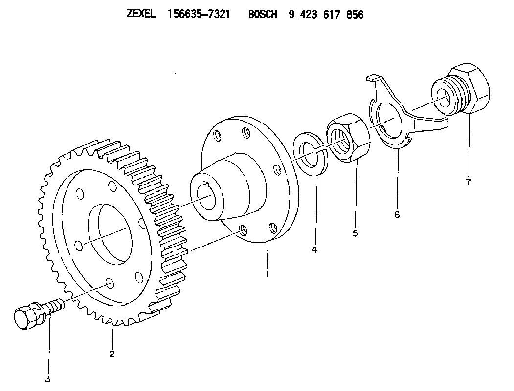
| 1. | [1] | 156612-1100 | COUPLING PLATE |
| 2. | [1] | 156211-5500 | TOOTHED GEAR |
| 3. | [6] | 139006-4300 | BLEEDER SCREW |
| 4. | [1] | 023641-2410 | LOCKING WASHER |
| 5. | [1] | 029231-2070 | UNION NUT |
| 6. | [1] | 156210-3500 | LOCKING LEVER |
| 7. | [1] | 029002-4010 | BLEEDER SCREW |
Cross reference number
Zexel num
Bosch num
Firm num
Name
156635-7321
9 423 617 856
8943433810 ISUZU
COUPLING PLATE
K 14GU COUPLING COUP
K 14GU COUPLING COUP
Information:
Use extreme care in keeping the work area and tools clean. Handle all parts with care to avoid any damage.
1. Place the nozzle in the holding tool (2) and secure the tool in a vise. Do not clamp any part of the nozzle body directly in the vise.
LOOSENING LOCKNUT
1. Locknut. 2. 8S2250 Nozzle Holding Tool.2. Loosen lift adjusting screw locknut (1). Loosen the lift adjusting screw two or three turns. Loosen pressure screw (3).
LOOSENING PRESSURE SCREW
3. Pressure screw.
PRESSURE SCREW ASSEMBLY REMOVED3. Holding the nozzle in one hand, invert it and back out the pressure screw allowing the spring, spring seat and shims to fall into your hand. The valve may slide out, by its own weight, and should be handled carefully by its stem.4. If the valve does not fall out, remove it with retractor (4). To prevent bending the valve, bottom it in the body with the retractor. Push down on the retractor body to mount the collet. Turn the knurled nut counterclockwise to secure the collet and withdraw the valve.
REMOVING VALVE
4. 5P958 Valve Retractor.5. Place the parts in solvent to loosen carbon and deposits of foreign material. Do not soak the body assembly in solvent for over 1 to 2 hours. The solvent can damage the epoxy bond used to secure the body assembly components together.Assemble Fuel Injection Nozzle (9L7883 Nozzles)
Before assembly, wash all parts thoroughly. Flush the body to remove any debris or lapping compound. Assemble while all parts are wet with clean fuel.1. Handle valve (1) by its shank and slide it partially into the body.
ASSEMBLENG NOZZLE
1. Valve. 2. Spring seat. 3. Spring. 4. Shims. 5. Pressure screw. 6. Locknut. 7. Lift adjusting screw.2. Assemble lift adjusting screw (7) into pressure screw (5) two to three turns and install locknut (6), do not tighten the locknut. Put shims (4), spring (3), and spring seat (2) on the lift adjusting screw. Put the thickest shim (4) against the screw.3. Tilt the nozzle body and with spring seat (2) in contact with the top of valve (1), push the valve and spring components into the body and tighten the pressure screw hand tight.4. Put the nozzle in the 8S2250 Nozzle Holding Tool. Put the holding tool in a vise and tighten the pressure screw (5) to 75 to 80 lb. in. (86.5 to 92.2 cm.kg).
TIGHTENING PRESSURE SCREW To check or adjust the opening pressure and the valve lift see the TESTING AND ADJUSTING section of the Service Manual.5. To tighten the locknut, hold lift adjusting screw (7) with a screwdriver and tighten the locknut (6) just enough so lift adjusting screw (7) will not turn.
TIGHTENING LOCKNUT6. Use a torque wrench and tighten the locknut to 35 to 40 lb. in. (40.4 to 46.1 cm.kg).
TIGHTENING LOCKNUTService And Inspect Fuel Injection Nozzle (9L7883 Nozzles)
1. Use the brush (4) to clean the tip and body exterior.2. Secure the 8S2247 Cleaning Wire [.008 to .009 in. (0.20 to 0.23 mm) dia.] in pin vise (1) with 1/32 in. (0.79 mm)
Have questions with 156635-7321?
Group cross 156635-7321 ZEXEL
Isuzu
156635-7321
9 423 617 856
8943433810
COUPLING PLATE