Information coupling plate
BOSCH
9 423 617 169
9423617169
ZEXEL
156635-2520
1566352520
KOMATSU
6131713170
6131713170
Rating:
Scheme ###:
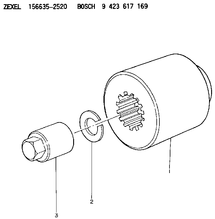
| 1. | [1] | 156635-2420 | COUPLING PLATE |
| 2. | [1] | 014111-2440 | LOCKING WASHER D21.5&12.2T3 |
| 3. | [1] | 131325-0500 | UNION NUT |
Include in #1:
101402-3440
as COUPLING PLATE
Cross reference number
Zexel num
Bosch num
Firm num
Name
156635-2520
9 423 617 169
6131713170 KOMATSU
COUPLING PLATE
K 14GU COUPLING COUP
K 14GU COUPLING COUP
Information:
Remove Timing Gears And Plate
start by:a) remove timing gear coverb) remove fuel injection pump and governor drive 1. Remove four bolts (2), plate (3) and idler gear (1).2. Use tooling (A) to remove camshaft gear (4).
Do not turn the crankshaft with camshaft gear removed. Damage can be caused to pistons and valves or both.
3. Remove bolts (5) that hold timing gear plate (6) to cylinder block.4. Remove timing gear plate (6). 5. Use tooling (B) to remove the bearing from the idler gear.Install Timing Gears And Plate
1. Install a new gasket on timing gear plate. 2. Put timing gear plate (1) in position on cylinder block and install the bolts that hold timing gear plate to cylinder block.4. Heat camshaft gear (2) to a maximum temperature of 600°F (315°C) and install it on the camshaft. 5. Use tooling (A) and install the bearing in the idler gear. Install the bearing to a depth of .06 .02 in. (1.5 0.5 mm) below the rear face of the idler gear.6. Install idler gear, plate and bolts. Be sure No. 1 cylinder is at top center on compression stroke. Install idler gear so the "V" mark (4) on idler gear is in alignment with "V" mark on crankshaft gear. The "K" marks (3) of camshaft gear can be seen at outer edges of idler gear.end by:a) install fuel injection pump and governor driveb) install timing gear cover
Have questions with 156635-2520?
Group cross 156635-2520 ZEXEL
Komatsu
156635-2520
9 423 617 169
6131713170
COUPLING PLATE