Information coupling plate
BOSCH
9 423 617 385
9423617385
ZEXEL
105664-2380
1056642380
Rating:
Scheme ###:
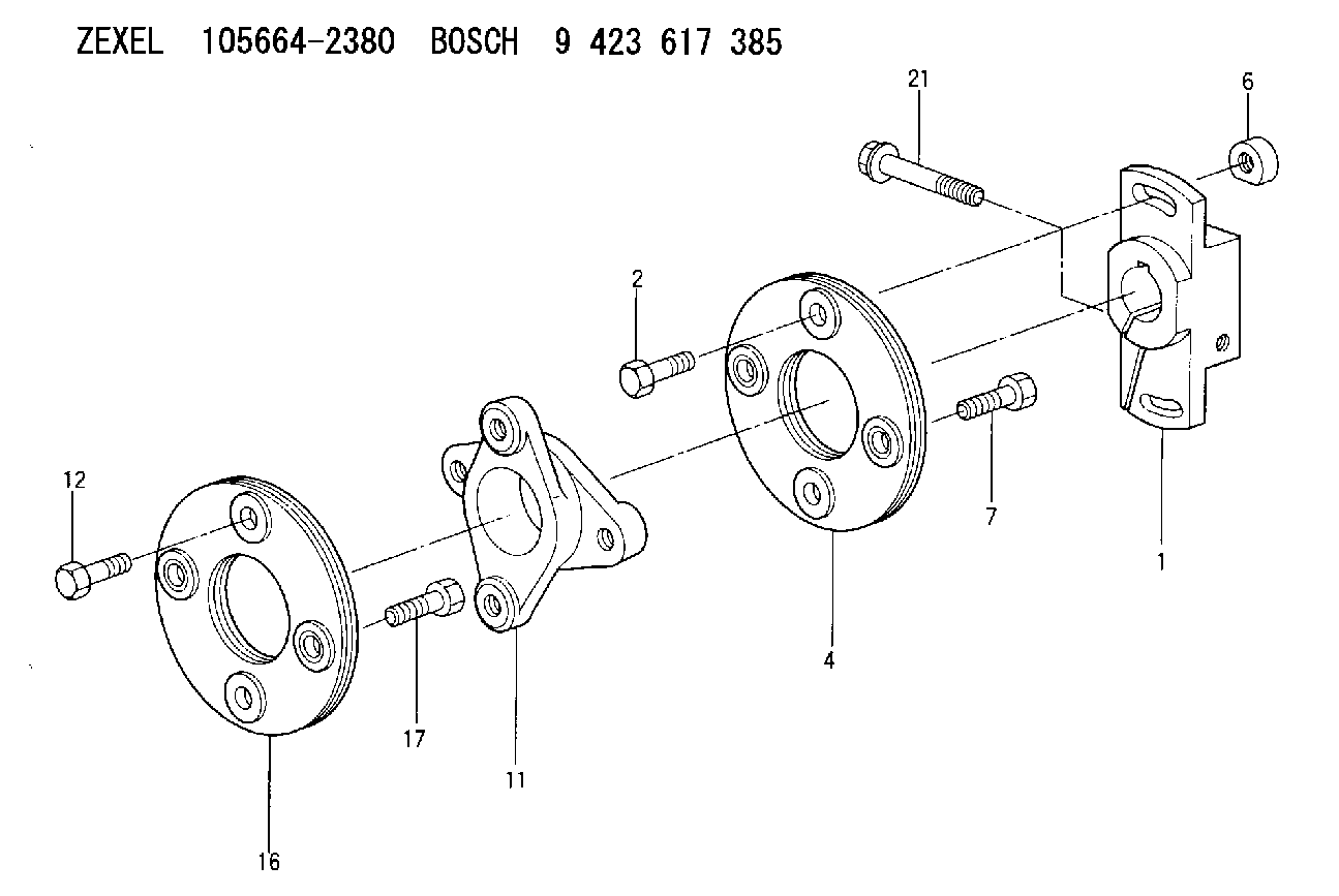
| 1. | [1] | 156632-5000 | COUPLING PLATE |
| 2. | [2] | 156634-4800 | BLEEDER SCREW |
| 4. | [1] | 156605-7620 | PLATE |
| 6. | [2] | 156617-4000 | UNION NUT |
| 7. | [2] | 156634-3800 | BLEEDER SCREW |
| 11. | [1] | 156628-5500 | COUPLING |
| 12. | [2] | 156634-3800 | BLEEDER SCREW |
| 16. | [1] | 156605-7620 | PLATE |
| 17. | [2] | 156634-3800 | BLEEDER SCREW |
| 21. | [1] | 156634-3900 | BLEEDER SCREW |
Include in #1:
106682-9621
as COUPLING PLATE
Cross reference number
Zexel num
Bosch num
Firm num
Name
Information:
Engine Lifting
When it is necessary to remove a component on an angle, remember that the capacity of an eyebolt is less as the angle between the supporting members and the object becomes less than 90 degrees. Eye Bolts and brackets should never be bent, and should only be loaded under tension.
Use a hoist to remove heavy components. Use an adjustable lifting beam to lift the engine. All supporting members (chains and cables) should be parallel to each other, and perpendicular as possible to the top of the object being lifted.Some removals require the use of lifting fixtures, to obtain proper balance and provide safe handling.To remove the engine ONLY, use the lifting eyes equipped with the engine.The lifting eyes are designed for the engine arrangement as sold. Modifying the lifting eyes and/or engine arrangement weight renders the lifting eyes and devices obsolete.If you modify the lifting eyes and/or engine arrangement weight, you are responsible for providing adequate lifting devices. Contact your Caterpillar dealer for information regarding fixtures for proper engine package lifting.Engine Storage
The following Engine Storage procedures and recommendations minimize the possibility of damage to engines stored for one year or less.When an engine is not started for several weeks, the lubricating oil drains from the cylinder walls and piston rings. Rust can then form on the cylinder liner surface, increasing engine wear and decreasing engine life.Special precautions should be used with engines remaining out of service for extended periods.After one year, a complete protection procedure must be followed if the engine is kept in storage longer. To prevent excessive engine wear:* Be sure all lubrication recommendations mentioned in the Maintenance Schedule intervals chart are completed.* If freezing temperatures are expected, check the cooling system for adequate protection against freezing. A 50/50 solution of Caterpillar (permanent-type) Antifreeze and approved water will give protection to -29°C (-20°F).If it will be impossible to start the engine periodically, consult your Caterpillar dealer for instructions to prepare your engine for longer storage periods.Refer to Storage Procedures For Caterpillar Products, SEHS9031, for more detailed information on engine storage.Engine and Marine Transmission Lifting
To remove the engine only, or the engine and marine gear together, use the lifting eyes on the engine.Marine Transmission Lifting
To remove the marine transmission only, use the eye bolts in the marine transmission housing.If a component resists removal, check to be certain all nuts and bolts have been removed and that an adjacent part is not interfering.Marine Transmission Storage
Transmission Storage Procedure
1. First, thoroughly clean the transmission and put on good quality paint.2. If the marine transmission is to be in storage for more than six months, add VCI oil at a rate of two percent of lube oil capacity. This will give additional protection from moisture.3. Operate the marine transmission for a short period to circulate oil.4. Cover and/or put tape over all openings.5. Put a heavy amount of multipurpose grease on all outside parts that move: linkage, etc.6. Put a waterproof or plastic cover over the unit.Transmission Procedure After Storage
1.