Information coupling plate
BOSCH
9 423 618 051
9423618051
ZEXEL
105662-1400
1056621400

Rating:
Scheme ###:
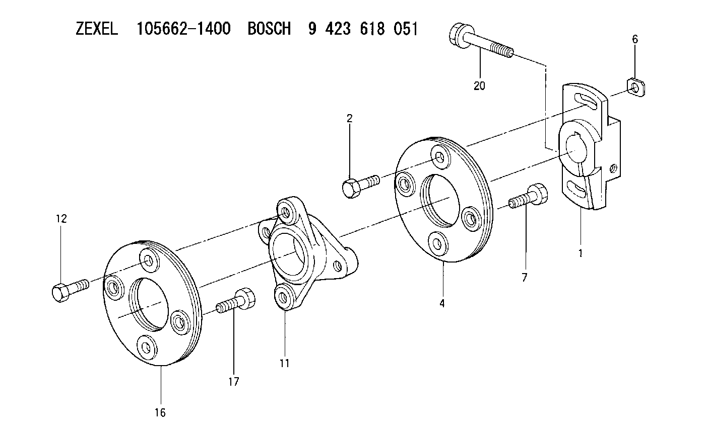
| 1. | [1] | 156631-6400 | COUPLING PLATE |
| 1. | [1] | 156631-6400 | COUPLING PLATE |
| 2. | [2] | 156603-5700 | BLEEDER SCREW |
| 2. | [2] | 156603-5700 | BLEEDER SCREW |
| 4. | [1] | 156605-2320 | PLATE |
| 4. | [1] | 156605-2320 | PLATE |
| 6. | [2] | 156617-2500 | UNION NUT |
| 6. | [2] | 156617-2500 | UNION NUT |
| 7. | [2] | 156633-8100 | BLEEDER SCREW M8P1.25L19 |
| 7. | [2] | 156633-8100 | BLEEDER SCREW M8P1.25L19 |
| 11. | [1] | 156609-7600 | COUPLING |
| 11. | [1] | 156609-7600 | COUPLING |
| 12. | [2] | 156633-8100 | BLEEDER SCREW M8P1.25L19 |
| 12. | [2] | 156633-8100 | BLEEDER SCREW M8P1.25L19 |
| 16. | [1] | 156605-2320 | PLATE |
| 16. | [1] | 156605-2320 | PLATE |
| 17. | [2] | 156633-9700 | BLEEDER SCREW |
| 17. | [2] | 156633-9700 | BLEEDER SCREW |
| 20. | [1] | 156633-1200 | BLEEDER SCREW |
| 20. | [1] | 156633-1200 | BLEEDER SCREW |
Cross reference number
Zexel num
Bosch num
Firm num
Name
105662-1400
9 423 618 051
COUPLING PLATE
K
K
Information:
When it is necessary to remove a component on an angle, remember that the capacity of an eyebolt is less as the angle between the supporting members and the object becomes less than 90 degrees. Eyebolts and brackets should never be bent and should only be loaded in tension.
Use a hoist to remove heavy components. Lift the engine by using an adjustable lifting beam. All supporting members (chains and cables) should be parallel to each other, and as near perpendicular as possible to the top of the object being lifted.Some removals require the use of lifting fixtures to obtain proper balance and to provide safe handling. To remove the engine ONLY, use the two lifting eyes equipped with the engine.Lifting eyes are designed for the engine arrangement as is. Alterations to lifting eyes and/or arrangement weight make the lifting devices and eyes obsolete. If you make alterations, you are responsible for providing adequate lifting devices.See your Caterpillar dealer or vessel OEM for information regarding fixtures for proper lifting of your complete engine power package.Engine and Marine Transmission Lifting
To remove the engine only or the engine and marine transmission together, use the two lifting eyes on the engine.Marine Transmission Lifting
To remove the marine transmission only, use the four permanent eyebolts in the marine transmission housing.If a component resists removal, check to be certain all nuts and bolts have been removed and that an adjacent part is not interfering.Engine Storage
These instructions give procedures and recommendations that will keep the possibility of damage at a minimum when engines are in storage for one year or less.If the engine will not be or has not been started for several weeks, the lubricating oil will drain from the cylinder walls and piston rings.If an engine remains out of service and its use is not immediately planned, special precautions should be taken. Rust can form on the cylinder liner surface, which will increase engine wear and may result in shorter engine life. To prevent this problem from becoming excessive, be sure all lubrication recommendations mentioned in the Maintenance Schedule are completed.After one year, a complete protection procedure must be followed if the engine is kept in storage longer. Refer to Storage Procedures For Caterpillar Products, SEHS9031 for more detailed information on engine storage.If freezing temperatures are expected, check the cooling system for adequate protection against freezing. A fifty/fifty solution of Caterpillar (permanent-type) Antifreeze and approved water will give protection to -29°C (-20°F).If it will be impossible to start the engine periodically, consult your Caterpillar dealer for instructions to prepare your engine for longer storage periods.If an engine remains out of service and its use is not immediately planned, special precautions should be taken. Refer to Storage Procedures For Caterpillar Products, SEHS9031 for more detailed information on engine storage.Recommendations After Engine Storage
1. Remove all outside protective covers, and any tape or grease used for protection.2. Drain the VCI oil1 and engine oil mixture from the engine. If the oil has been in the engine for
Have questions with 105662-1400?
Group cross 105662-1400 ZEXEL
105662-1400
9 423 618 051
COUPLING PLATE