Information coupling plate
BOSCH
9 423 617 419
9423617419
ZEXEL
105661-4250
1056614250
MITSUBISHI
3006161012
3006161012

Rating:
Scheme ###:
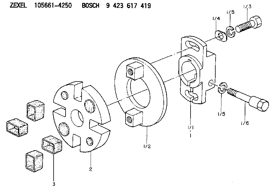
| 1. | [1] | 156630-2320 | COUPLING PLATE |
| 1/1. | [1] | 156630-2300 | COUPLING PLATE |
| 1/2. | [1] | 156602-0200 | JAW COUPLING |
| 1/3. | [2] | 156603-4400 | BLEEDER SCREW |
| 1/4. | [2] | 156615-0700 | PLAIN WASHER |
| 1/5. | [3] | 014110-8440 | LOCKING WASHER |
| 1/5. | [3] | 014110-8440 | LOCKING WASHER |
| 1/6. | [1] | 156633-1100 | BLEEDER SCREW |
| 2. | [1] | 156609-0120 | SLOTTED WASHER |
| 3. | [4] | 156610-1300 | BUSHING |
Cross reference number
Zexel num
Bosch num
Firm num
Name
105661-4250
9 423 617 419
3006161012 MITSUBISHI
COUPLING PLATE
K 14GT COUPLING COUP
K 14GT COUPLING COUP
Information:
Start By:
Do not let the tops of the nozzles turn while the fuel lines are loosened. The nozzles will be damaged if the top of the nozzle turns in the body. Defective fuel nozzles will damage the engine due to improper spray patterns.
a. remove fuel injection lines
Keep all parts clean from contaminants. Contaminants put into the system may cause rapid wear and shortened component life.
1. Remove clamp (1). 2. Install tool (A). Turn screw (2) out until the button on the screw almost makes contact with the inside of the nozzle puller. Tilt the tool approximately 45° and place it over the nozzle.3. Tilt the nozzle puller (A) up so the inside lip of the puller is under the stepped diameter of the nozzle.4. Turn screw (2) down until the button goes into the bolt hole for the nozzle hold down clamp.
Do not exceed a torque of 17 N m (13 lb ft) on the screw in tooling (A) to remove the nozzle. Added force can cause the stem of the nozzle to bend or break off.
5. Turn screw (2) to lift the nozzle out of its bore. If necessary, after the nozzle is loose in its bore, move it up and down to help loosen any carbon and make removal easier. 6. If the nozzle can not be removed with tooling (A), tooling (B) must be used. When tooling (B) is used, the nozzle normally can not be used again, and a new nozzle will need to be installed as a replacement.
Hold tool (B) so the center line of tool (B) is the same as the extended center line of fuel injection nozzle (2). This will prevent distortion of the fuel injection nozzle which can cause the nozzle to bend or break off.
7. Remove the protective cap and install tooling (B).8. Use the slide hammer to remove fuel injection nozzle (3).9. Remove the compression seal.10. For nozzles removed using tool (A), remove the carbon dam seal on the end of the nozzle. The following steps are for the installation of the fuel injection nozzles. Tool (C) must be modified by drilling it out to a diameter of 8.5 mm (.344 in) and to a depth of 1.5 mm (.060 in) before it can be used on the 8N7002 Fuel Injection Nozzle.11. Use tool (C) to install carbon dam seal (4).12. To clean the nozzles, see Special Instruction SEHS7292 for the use of tooling (D).13. Install new compression seal (5). 14. Use tool (E) to clean the bore for the fuel injection nozzle. 15. Install fuel injection nozzle (6).
Do not let the tops of the fuel nozzles turn when the fuel lines are tightened. The nozzles will be damaged if the top of the nozzle turns in the body.
End By:a. install fuel injection lines
Have questions with 105661-4250?
Group cross 105661-4250 ZEXEL
Mitsubishi
105661-4250
9 423 617 419
3006161012
COUPLING PLATE