Information coupling plate
BOSCH
9 423 617 001
9423617001
ZEXEL
105661-0340
1056610340
ISUZU
5157800020
5157800020
Rating:
Cross reference number
Zexel num
Bosch num
Firm num
Name
105661-0340
9 423 617 001
5157800020 ISUZU
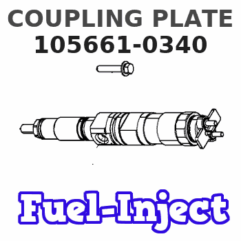
COUPLING PLATE
* K 14GT COUPLING COUP
* K 14GT COUPLING COUP
Information:
START BY:a. remove valve coversb. remove rocker shaft assemblies and pushrodsc. remove fuel injection nozzles (earlier)
Be sure that the piston is at Top Center so that the valves will be held in position when the springs are removed.
1. Remove the valve cover bases.2. Remove the valve stem locks with tooling (A) using the following procedure: a. Install adapter plate (1) with two OS1618 (5/16-18 x 1 in.) bolts.b. Install stud (2) and nut (3). Tighten the nut. c. Install plate (4), washer (5) and nut (6). Tighten the nut until the locks are free.d. Remove locks (7), and remove the nut, washer and plate from the stud. Remove the stud and adapter plate from the fuel injection nozzle adapter. 3. Remove rotocoil (8), spring (9) and washer (10). 4. Use tool (B) to remove fuel injection nozzle adapter (11) from the cylinder head assembly. 5. Remove washers (12) and seals (13) from adapters (11).Install Fuel Injection Nozzle Adapters (Earlier)
1. Inspect seals (3) for damage or wear, and make a replacement if necessary.2. Install washers (1) and seals (3) on adapters (2).3. Put liquid soap in the bores of the cylinder head and on the seals of the fuel injection nozzle adapters.4. Put 5P3931 Anti-Seize Compound on the threads of adapter (2), and install the adapters in the cylinder head assembly. 5. Use tool (A), and tighten the adapters to a torque of 205 14 N m (150 10 lb.ft.). 6. Install washers (6), springs (5) and rotocoils (4). 7. Use tool (B), and compress the springs until locks (7) can be installed. Install locks (7) on the valve stems, and remove tool (B).8. Install the valve cover base. Tighten the valve cover base mounting bolts to a torque of 14 3 N m (10 2 lb.ft.).END BY:a. install fuel injection nozzles (earlier)b. install rocker shaft assemblies and push rodsc. install valve covers
Have questions with 105661-0340?
Group cross 105661-0340 ZEXEL
Hino
Isuzu
105661-0340
9 423 617 001
5157800020
COUPLING PLATE