Information coupling plate
BOSCH
9 423 618 250
9423618250
ZEXEL
105661-0250
1056610250
HINO
226001330A
226001330a

Rating:
Scheme ###:
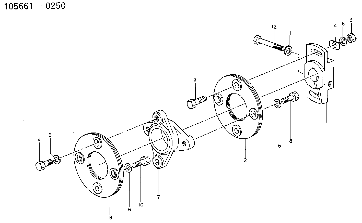
| 1. | [1] | 156630-5100 | COUPLING PLATE |
| 2. | [1] | 156605-2520 | PLATE |
| 3. | [2] | 156633-2400 | BLEEDER SCREW |
| 4. | [2] | 156615-2500 | PLAIN WASHER |
| 5. | [2] | 029200-8050 | UNION NUT |
| 6. | [6] | 014110-8440 | LOCKING WASHER |
| 6. | [6] | 014110-8440 | LOCKING WASHER |
| 6. | [6] | 014110-8440 | LOCKING WASHER |
| 6. | [6] | 014110-8440 | LOCKING WASHER |
| 7. | [1] | 156609-4300 | COUPLING |
| 8. | [4] | 156633-2500 | BLEEDER SCREW |
| 8. | [4] | 156633-2500 | BLEEDER SCREW |
| 9. | [1] | 156605-2620 | PLATE |
| 10. | [2] | 156633-6200 | BLEEDER SCREW |
| 11. | [1] | 156603-7900 | BLEEDER SCREW |
| 12. | [1] | 029320-8040 | LOCKING WASHER |
Cross reference number
Zexel num
Bosch num
Firm num
Name
105661-0250
9 423 618 250
226001330A HINO
COUPLING PLATE
* K 14GT COUPLING COUP
* K 14GT COUPLING COUP
Information:
1. Disconnect fuel line (1) from the fuel transfer pump. Disconnect fuel line (2) from the fuel injection pump housing. Remove line (3) from the fuel ratio control and aftercooler housing. 2. Disconnect fuel injection lines (4) from the fuel injection pump housing.
Do not disconnect the air line from the air compressor governor until the air pressure is zero.
3. Loosen the bleed valves, and release the air pressure in the air tank. 4. Remove air line (5). Remove coolant line (6). 5. The weight of the fuel injection pump housing and governor is 57 kg (125 lb.). Attach a hoist to the fuel injection pump housing, and remove bolts (7). 6. Remove the two nuts and two bolts (8) and bolt (9). Remove fuel injection pump housing and governor (10). 7. Remove O-ring seals (11) from the fuel injection pump housing.Install Fuel Injection Pump Housing And Governor
1. Attach a hoist to the fuel injection pump housing and governor (1). Be sure that the three O-ring seals are in position in the fuel injection pump housing. Install the fuel injection pump housing and governor on the timing gear housing. 2. Connect air line (2) and water line (3) to the air compressor. 3. Connect fuel injection lines (4) to fuel injection pump housing, and tighten the fuel injection line nuts to a torque of 40 7 N m (30 5 lb.ft.) with tool (C). 4. Connect fuel line (5) to fuel injection pump housing, and connect fuel line (6) to the fuel transfer pump. Install line (7) between the fuel ratio control and aftercooler housing. For timing of the fuel injection pump, see Install Automatic Timing Advance.END BY:a. install automatic timing advance
Have questions with 105661-0250?
Group cross 105661-0250 ZEXEL
Mitsubishi
Hino
Mitsubishi
Hino
105661-0250
9 423 618 250
226001330A
COUPLING PLATE