Information coupling plate
BOSCH
9 423 618 249
9423618249
ZEXEL
105661-0150
1056610150
HINO
6072160090
6072160090
Rating:
Scheme ###:
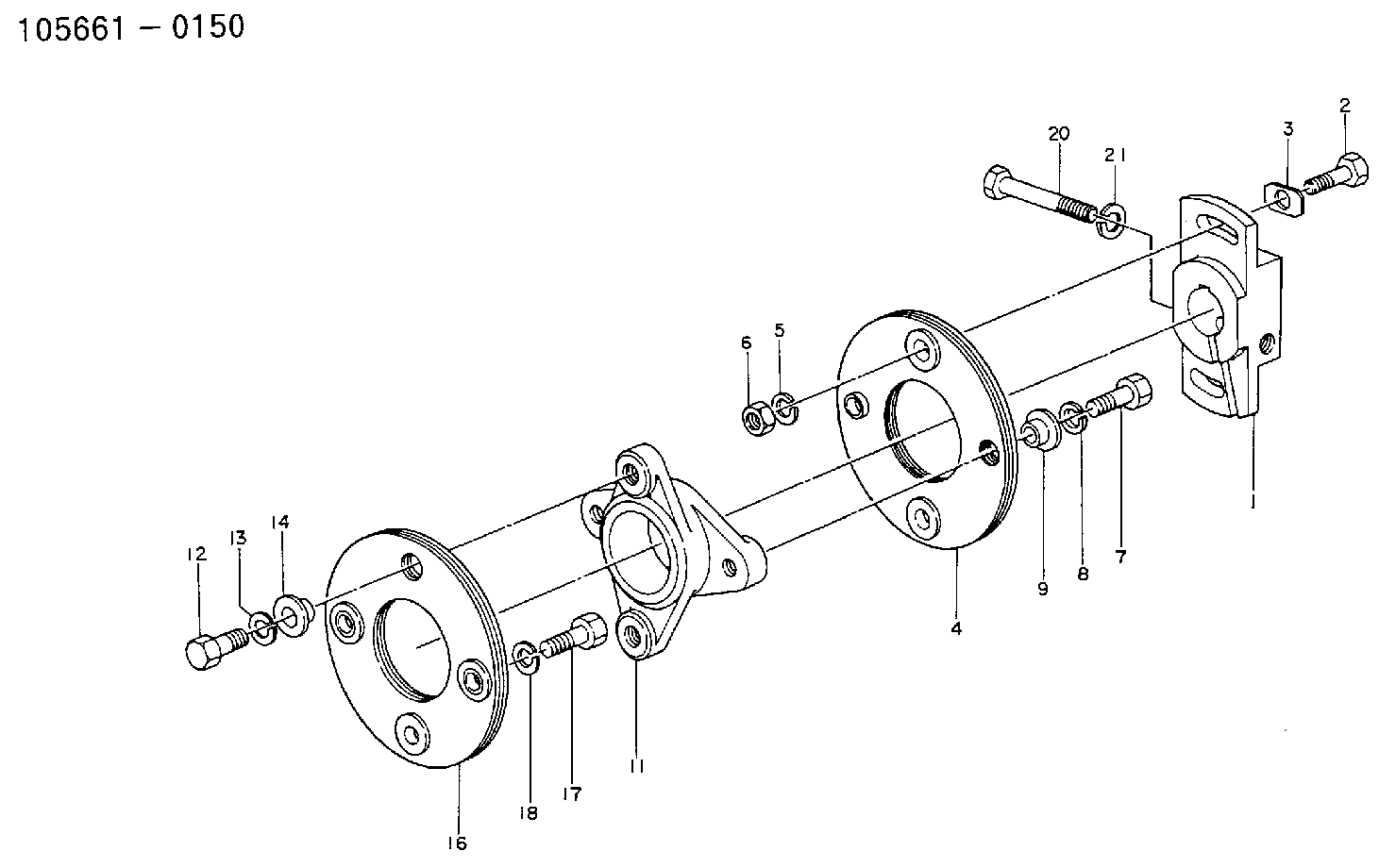
| 1. | [1] | 156630-0600 | COUPLING PLATE |
| 2. | [2] | 156603-4400 | BLEEDER SCREW |
| 3. | [2] | 156615-0700 | PLAIN WASHER |
| 4. | [1] | 156605-1120 | PLATE |
| 5. | [2] | 014110-8440 | LOCKING WASHER |
| 6. | [2] | 029200-8050 | UNION NUT |
| 7. | [2] | 156633-0500 | BLEEDER SCREW |
| 8. | [2] | 014110-8440 | LOCKING WASHER |
| 9. | [2] | 156622-1100 | BUSHING |
| 11. | [1] | 156609-2800 | COUPLING |
| 12. | [2] | 156633-0500 | BLEEDER SCREW |
| 13. | [2] | 014110-8440 | LOCKING WASHER |
| 14. | [2] | 156622-1100 | BUSHING |
| 16. | [1] | 156605-2120 | PLATE |
| 17. | [2] | 156603-9700 | BLEEDER SCREW |
| 18. | [2] | 014110-8440 | LOCKING WASHER |
| 20. | [1] | 156603-7900 | BLEEDER SCREW |
| 21. | [1] | 029320-8040 | LOCKING WASHER |
Include in #1:
101693-2460
as COUPLING PLATE
Cross reference number
Zexel num
Bosch num
Firm num
Name
105661-0150
9 423 618 249
6072160090 HINO
COUPLING PLATE
K 14GT COUPLING COUP
K 14GT COUPLING COUP
105661-0150
9 423 618 249
226001240A HINO
COUPLING PLATE
A K 14GT COUPLING COUP
A K 14GT COUPLING COUP
Information:
START BY:a. remove valve coversb. remove fuel injection lines 1. Use tool (A) and a 5P328 crowfoot wrench (7/8") to loosen the fuel injection line nut at the nozzle end.
Do not let the tops of the fuel nozzles turn when the fuel lines are loosened. The nozzles will be damaged if the top of the nozzles turn in the body.
2. Use tool (B) to loosen the nut at the fuel injection line adapter end. Remove inner fuel injection lines (1). Install plugs in the fuel injection nozzles. 3. Remove the nut that holds the adapters to the cylinder head assembly. Remove fuel injection line adapters (2).Install Fuel Injection Line Adapters
1. Check the condition of O-ring seal (1) on fuel injection line adapter (2) for damage. Make a replacement if necessary.2. Lubricate O-ring seal (1) with clean engine oil. Install fuel injection line adapter (2). Tighten the retaining nut to a torque of 13.6 2.7 N m (10 2 lb.ft.). 3. Check the condition of the O-ring seal on inner fuel line (3) for damage, and make a replacement if necessary. Install inner fuel line (3).
Do not let the tops of the fuel nozzles turn when the fuel lines are tightened. The nozzles will be damaged if the top of the nozzles turn in the body.
4. Use tooling (A) to tighten the inner fuel line nuts to a torque of 40 7 N m (30 5 lb.ft.).END BY:a. install fuel injection linesb. install valve covers
Have questions with 105661-0150?
Group cross 105661-0150 ZEXEL
Hino
105661-0150
9 423 618 249
6072160090
COUPLING PLATE
105661-0150
9 423 618 249
226001240A
COUPLING PLATE