Information control unit
BOSCH
F 01G 090 1F1
f01g0901f1
ZEXEL
407915-5810
4079155810
ISUZU
1815107810
1815107810

Rating:
Compare Prices: .
As an associate, we earn commssions on qualifying purchases through the links below

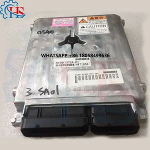
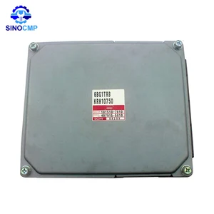
Controller KRH10750 KRH10010 181510-7810 407915-5810 For Sumitomo SH120-3 SH200-3 SH210-3 A3 Excavator For Case CX210 Engine For ISUZU 6BG1 Engine For Mitsubishi 6D16 6D24 Engine
SXCCGMGQ Part Name:Controller || Part Number:KRH10750 KRH10010 181510-7810 407915-5810 || Application: For Sumitomo SH120-3 SH200-3 SH210-3 A3 Excavator For Case CX210 Engine For ISUZU 6BG1 Engine For Mitsubishi 6D16 6D24 Engine || Tips: This Product Requires Programming Code To Be Written. Please Send Us the following information: Engine Nameplate, Machine Serial Number nameplate, ECM Part Number || Easy installation: Standardized interface design, easy installation, no additional modification, users can easily complete replacement and maintenance.
SXCCGMGQ Part Name:Controller || Part Number:KRH10750 KRH10010 181510-7810 407915-5810 || Application: For Sumitomo SH120-3 SH200-3 SH210-3 A3 Excavator For Case CX210 Engine For ISUZU 6BG1 Engine For Mitsubishi 6D16 6D24 Engine || Tips: This Product Requires Programming Code To Be Written. Please Send Us the following information: Engine Nameplate, Machine Serial Number nameplate, ECM Part Number || Easy installation: Standardized interface design, easy installation, no additional modification, users can easily complete replacement and maintenance.

$1,560.52
08 Nov 2024
12.0681[5.43] pounds
CN: gyuhgu5
DFGUFG KRH10750 KRH10010 181510-7810 407915-5810 ECU. Compatible For Sumitomo SH120-3 SH200-3 SH210-3 A3. Car 6D16 6D24 6BG1 Excavator Engine Computer Board ECM Electronic Control Module
DFGUFG OE NO. : KRH10750 KRH10010 181510-7810 407915-5810 || Durable and Reliable Design: Built with qualified materials, ensuring long-lasting performance even in harsh driving conditions. Tested for durability, so can trust it for consistent results over time. || It is an electronic device that controls various components of an internal combustion engine. || Item Type : Drive Elements. || Origin : Mainland China.
DFGUFG OE NO. : KRH10750 KRH10010 181510-7810 407915-5810 || Durable and Reliable Design: Built with qualified materials, ensuring long-lasting performance even in harsh driving conditions. Tested for durability, so can trust it for consistent results over time. || It is an electronic device that controls various components of an internal combustion engine. || Item Type : Drive Elements. || Origin : Mainland China.
$1,079.10
24 Nov 2024
12.0681[5.43] pounds
CN: gyuhgu5
DFGUFG KRH10750 KRH10010 181510-7810 407915-5810 ECU. Compatible For Case CX210. Car 6D16 6D24 6BG1 Excavator Engine Computer Board ECM Electronic Control Module
DFGUFG OE NO. : KRH10750 KRH10010 181510-7810 407915-5810 || Durable and Reliable Design: Built with qualified materials, ensuring long-lasting performance even in harsh driving conditions. Tested for durability, so can trust it for consistent results over time. || It is an electronic device that controls various components of an internal combustion engine. || Item Type : Drive Elements. || Origin : Mainland China.
DFGUFG OE NO. : KRH10750 KRH10010 181510-7810 407915-5810 || Durable and Reliable Design: Built with qualified materials, ensuring long-lasting performance even in harsh driving conditions. Tested for durability, so can trust it for consistent results over time. || It is an electronic device that controls various components of an internal combustion engine. || Item Type : Drive Elements. || Origin : Mainland China.
You can express buy:
USD 545.59
14-06-2025
14-06-2025
HS Highest Quality ECU 4HK1 6HK1 Controller 1815107810 8981530572 for ISUZU for Sumitomo SH200-5 Js220 Js200 Zx200-3 Zx240-3
USD 1490
13-05-2025
13-05-2025
6D16 6D24 4BG1 Controller KRH10750 KRH10010 181510-7810 407915-5810 for Sumitomo SH120-3 SH200-3 SH210-3 A3 Excavator Case CX210
Images:
USD 1383.89

[14-Jun-2025]
USD 1810.71

[12-Nov-2023]
USD 2100

[02-Dec-2018]
USD 2000

[20-Jun-2019]
Cross reference number
Zexel num
Bosch num
Firm num
Name
Information:
Oiler Feed Adjustment
If necessary, adjust the lubricator to release approximately four drops of fluid per minute into the starting motor air stream. Be sure there is NO fuel supply to the engine. 1. Push on the air start control lever (1) to crank the engine.2. Count the drops of fluid per minute that are released into the air stream. Turn the needle valve knob (3) counterclockwise to increase the flow and clockwise to decrease the flow of fluid into the air stream.Collector Bowl
Some air starters may be equipped with a collector bowl. The bowl collects used oil after the oil has lubricated the vanes. The bowl also collects moisture condensation from the compressed air. When the collector bowl becomes half full, drain the used lubricant. Never fill the lubricator bowl with oil from the collector bowl- use clean lubricant.Air Tank (If Equipped)
For good life of the air starting motor, the air supply must be free of dirt and water. The air starter requires adequate air pressure in order to operate.* Drain water from the air tank (if equipped). Open the drain valve on the bottom of the air tank to drain the condensation and oil carryover.* Check the air supply pressure. The air starting motor requires a minimum of 620 kPa (90 psi) of air pressure to operate properly. The maximum air pressure must not exceed 1550 kPa (225 psi). The normal air pressure will be 758 kPa (110 psi) to 965 kPa (140 psi).Engine Air Cleaner
Check Air Cleaner Service Indicator
Typical air cleaner indicator, mounted on the air cleaner housing. Your engine may be equipped with a different indicator.A service indicator (if equipped) may be mounted on the air cleaner or in a remote location. A colored piston showing in the window indicates the need for servicing the air cleaner. Observe the air cleaner service indicator. Clean or replace the air cleaner element when the yellow diaphragm enters the red zone or the red piston locks in the visible position. If the air cleaner indicator shows red at any time, clean the filter element or install a new air cleaner element.
Never service the air cleaner with the engine running since this will allow dirt to enter the engine.
If your air cleaner element becomes plugged, the air can split the element filter material. Unfiltered air will drastically accelerate internal engine wear. Your Caterpillar dealer has air filter elements to service this unit. Contact your Caterpillar dealer for the correct filter element. If equipped with a Light Duty air cleaner element, refer to the 50 Hour interval for information.Single Stage Air Cleaner Elements
Remove and Install Air Cleaner Elements
1. Remove the air cleaner cover (1) and element (2).2. Seal the turbocharger air inlet (3) so that debris can not enter the inlet. Use tape, or secure a clean cloth over the opening.3. Clean the inside of the air cleaner cover and body.4. Inspect the replacement element for damage, dirt or debris.5. Remove the seal from the turbocharger inlet.6. Install a clean,