Information control lever
BOSCH
9 421 615 706
9421615706
ZEXEL
159263-6400
1592636400
ISUZU
8970269250
8970269250
Rating:
Include in ###:
Cross reference number
Zexel num
Bosch num
Firm num
Name
159263-6400
9 421 615 706
8970269250 ISUZU
CONTROL LEVER
C 14GJ LEVER GOV
C 14GJ LEVER GOV
159263-6400
9 421 615 706
1926389TA0 NISSAN
CONTROL LEVER
C 14GJ LEVER GOV
C 14GJ LEVER GOV
Information:
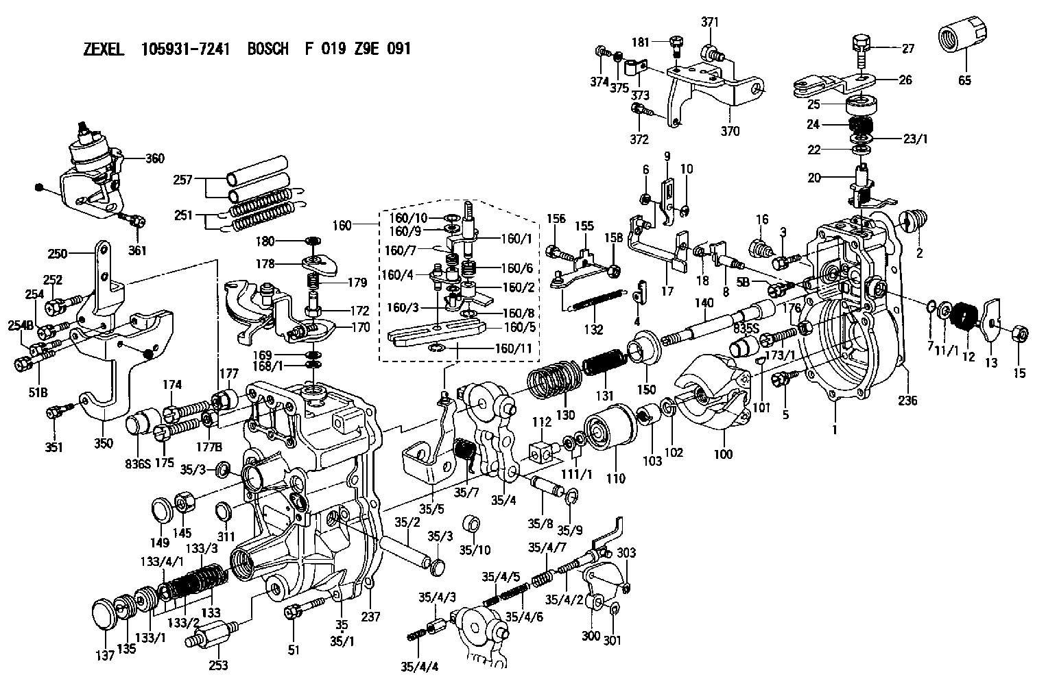
3. Install dowel (5) in governor shaft (6). Install the governor shaft in the carrier as shown. 4. Put the carrier in position on the camshaft. Install the bolts that hold the carrier in place.
Replace shield (7) with a new part any time it is removed.
5. Install shield (7) on the carrier, and use Tool (A) to push the shield against its seat. Use a hammer and punch to stake the metal in two places on the side of the shield 180° 5° apart next to the holes in the shield. 6. Install one race (9), bearing (10), the other race (9), and use Tool (B) to install the ring on riser (8) as shown. 7. Install riser (8) and the spring (overfueling spring) on the governor shaft as shown. 8. Assemble the dashpot as follows:a. Install spring (12) on seat (11). Install seat (13) in spring (12).b. Put spool (14) and ring (15) in position on seat (13). Use Tool (B) to install snap ring (16) to hold them in place. 9. Install dashpot assembly (17) on the governor shaft as shown. 10. Install ring (21) in the lower groove in the governor shaft. Install one sleeve (20), spring (19), the other sleeve (20) and bearing (18) on the governor shaft as shown. Spring (19) is used to put a preload on the thrust bearing on the camshaft in the fuel injection pump housing.11. Use Tool (C) to hold spring (19) under compression. Install ring (22) in the groove in the governor shaft. Remove Tool (C). 12. Put lever (27) in position on governor servo (23). Install pin (24) to hold the lever in place. Use a hammer and chisel to stake the metal four places 90° apart on the outside surface on both legs of the governor servo to hold pin (24) in place.13. Install the O-ring seal on sleeve (25). Install piston (26) and sleeve (25) in the governor servo as shown. 14. Install valve (28) in the governor servo as shown. 15. Install one lockring (32) in the groove near the center of valve (28). Put sleeve (29), spring (broken link spring) (30) and seat (31) in position on valve (28). Install the other lockring (32) to hold the components in place. 16. Put the governor servo in position on the fuel injection pump housing with piston (26) engaged over rack (33). Install the bolts that hold the governor servo in place. The 3306 Engine has two adjustment screws and lock nuts.17. Install torque rise adjustment screw (36) in collar (34) as shown. Install locknut (35) on the screw. 18. Install bolt (38) in block (40) as shown. Install spring (37) on bolt (38) as shown. Put collar (34) in position on bolt (38) with the hole in the collar
Have questions with 159263-6400?
Group cross 159263-6400 ZEXEL
Isuzu
159263-6400
9 421 615 706
8970269250
CONTROL LEVER
Nissan
159263-6400
9 421 615 706
1926389TA0
CONTROL LEVER