Information control lever
BOSCH
9 421 617 849
9421617849
ZEXEL
159202-3720
1592023720
HINO
223171670A
223171670a
Rating:
Include in ###:
Cross reference number
Zexel num
Bosch num
Firm num
Name
159202-3720
9 421 617 849
223171670A HINO
CONTROL LEVER
C 14GJ LEVER GOV
C 14GJ LEVER GOV
Information:
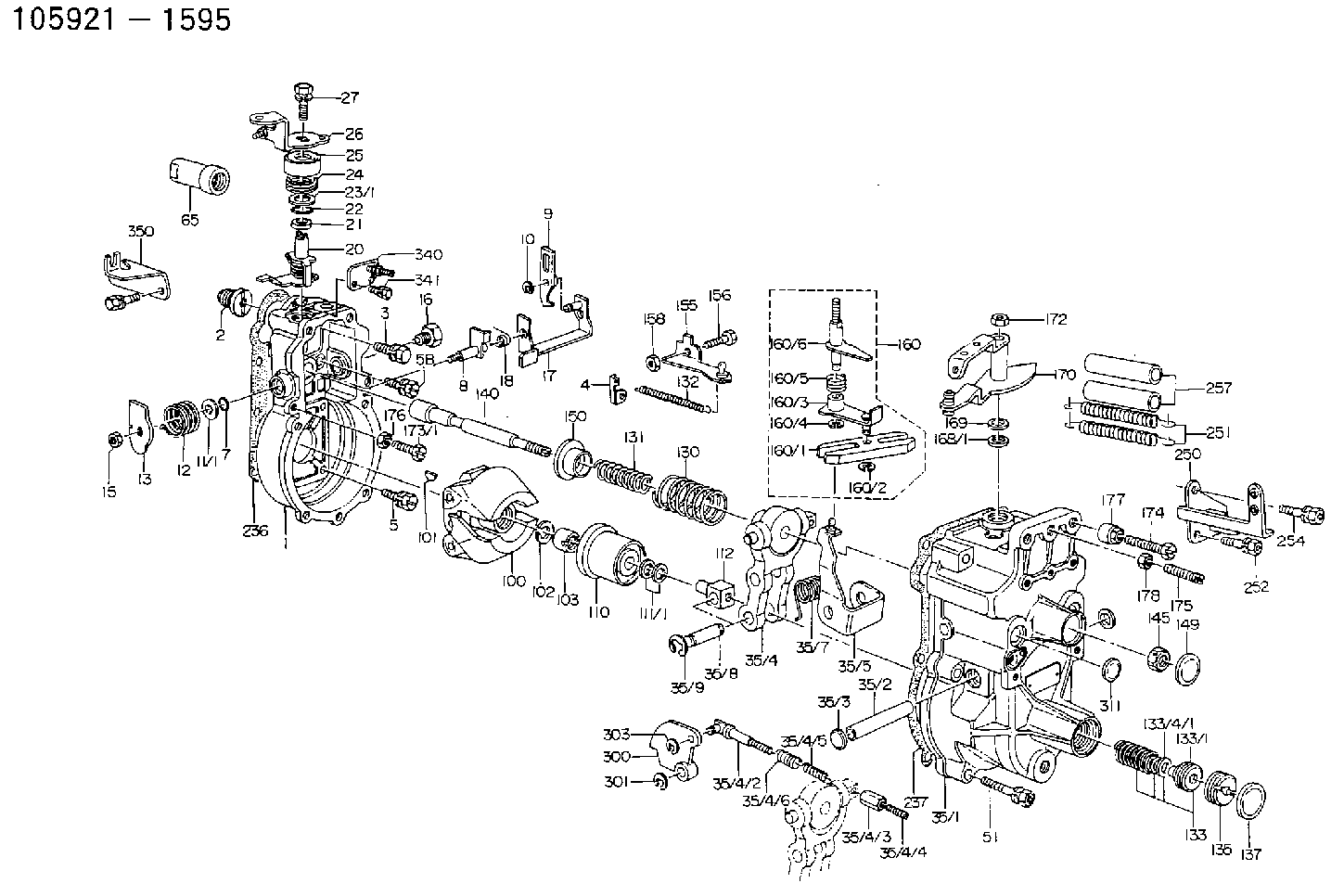
14. Put clean engine oil on the camshaft bearings and on camshaft (21). Install camshaft as shown. 15. Install camshaft gear (22) and retainer (23). Install the three bolts. 16. Put clean engine oil on lifters (25). Install lifters (25) and spacers (24) for each of the injection pumps. Be sure the lifters and spacers are put in their original location. 17. Put clean engine oil on the left and right fuel racks. Install left rack in the pump housing with the groove in the rack engaged with the tab of the rack bearing. Install right rack (26) with the groove in the rack engaged with the tab of the rack bearing. 18. Install dowel (27) in the pump housing until it is extended 12.2 0.5 mm (.48 .02 in) from the surface of the pump housing.19. Install link (29) and bracket assembly (30). Install bolt (28). Be careful so bracket (30) does not turn as bolt (28) is tightened. 20. Install Tool (E) in the injection pump housing to hold the racks in the center (zero) position.21. Put the space in gear segment (32) in alignment with the groove in pump barrel (31). Put the injection pump straight down into the housing bore with the space in gear segment (32) engaged with the pin in the lifter and the groove in barrel (31) engaged with the dowel in the pump housing. Use Tool (F) to install the pump. 22. Install seal (33) and bushing (34) in the pump housing bore. If the injection pump is in the correct position, bushing (34) will turn into the threads of the pump housing with the fingers until it is even with the housing.23. Tighten bushings (34) to a torque of 205 14 N m (150 10 lb ft) with Tool (G). 24. Install a felt washer (35) and protection caps for each injection pump. For more detail see the topic "Install Fuel Injection Pumps" in this module. 25. Heat gear (36) to a maximum temperature of 232°C (450°F) and install it on the shaft. 26. Install bearing in housing (37) with Tooling (C). 27. Install shaft and gear assembly (40) in fuel injection housing. Install gasket (39) on housing. Install small cover (38). Install housing (37) on fuel injection housing with the bolts that hold it. 28. Install fuel transfer pump (41) in housing (37) with the bolts that hold it. 29. If replacement of the dowels (43) in the governor plate is necessary, see illustration A42792P1 for correct installation dimensions. 30. Install bearing (42) for drive gear with Tooling (C) until it is 0.51 mm (.020 in) from the top surface of the governor plate. 31. Install drive gear (44), install ring (45) with Tool (H). 32. Install O-ring seals (47) on cylinder (46). 33. Install cylinder (46) in governor plate with the notch in the cylinder in alignment with the bolt hole in the governor plate. 34. Install O-ring seal (49) on sleeve (51).
Have questions with 159202-3720?
Group cross 159202-3720 ZEXEL
Hino
159202-3720
9 421 617 849
223171670A
CONTROL LEVER