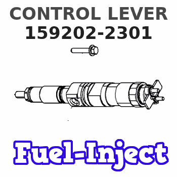
Information control lever
BOSCH
9 421 613 126
9421613126
ZEXEL
159202-2301
1592022301
ISUZU
1157253561
1157253561
Rating:
Include in ###:
Cross reference number
Zexel num
Bosch num
Firm num
Name
159202-2301
9 421 613 126
1157253561 ISUZU
CONTROL LEVER
C 14GJ LEVER GOV
C 14GJ LEVER GOV
159202-2301
9 421 613 126
223172690A HINO
CONTROL LEVER
C 14GJ LEVER GOV
C 14GJ LEVER GOV
159202-2301
9 421 613 126
ME730660 MITSUBISHI
CONTROL LEVER
C 14GJ LEVER GOV
C 14GJ LEVER GOV
159202-2301
9 421 613 126
19334Z9709 NISSAN-DIESEL
CONTROL LEVER
C 14GJ LEVER GOV
C 14GJ LEVER GOV
Information:
Start By:a. remove valve covers
Do not let the tops of the fuel injection nozzles turn when the fuel lines are loosened. The nozzles will be damaged if the top of the nozzles turn in the body.
1. Use Tooling (A) to loosen the nuts on the fuel injection line.2. Remove fuel injection lines (1).3. Disconnect fuel injection line nut (2) from head adapter nut (3).4. Remove adapter nut (3) and the O-ring seal. 5. Remove four bolts (4) that hold rocker arm assembly (5), and remove rocker arm assembly (5).Install Rocker Shaft Assemblies
1. Check the adjustment of the valve bridges. See the topic "Install Push Rods, Valve Lifters & Valve Bridges" in this module. 2. Loosen all the rocker arm adjusting screws on rocker shaft assembly (5).3. Install rocker shaft assembly (5).4. Clean the bolts that hold the rocker shaft assembly. Put 2P-2506 Thread Lubricant on the bolt threads, and install them.5. Be sure the rocker arms and push rods are in alignment before the rocker shaft assembly bolts are tightened.6. Tighten the rocker shaft bolts in the following sequence.a. Tighten bolts (1) through (4) in numerical sequence to a torque of 280 27 N m (210 20 lb ft).b. Tighten bolts (1) through (4) in numerical sequence to a torque of 440 20 N m (320 15 lb ft).c. Tighten bolts (1) through (4) in numerical sequence again to a final torque of 440 20 N m (320 15 lb ft). 7. Install a new O-ring seal on head adapter (7), and put clean engine oil on it.8. Put fuel injection line (8) in position, but do not tighten the nuts.9. Install adapters (7), and connect fuel injection lines (8).10. Connect fuel injection lines (6) to adapters (7).
Do not let the tops of the fuel injection nozzles turn when the fuel lines are tightened. The nozzles will be damaged if the top of the nozzles turn in the body.
11. Use Tooling (A) to tighten the fuel injection line nuts to a torque of 41 7 N m (30 5 lb ft).12. Adjust the valve clearance settings. The clearance for the intake valve is 0.38 mm (.015 in). The clearance for the exhaust valves is 0.76 mm (.030 in). See the topic "Valve Clearance Setting" in Testing & Adjusting.End By:a. install valve coversDisassemble Rocker Shaft Assemblies
Start By:a. remove rocker shaft assemblies 1. Remove retainer (1) from the end of the shaft.2. Remove the washers and rocker arm (2). 3. Use Tool (A) to remove the pin that holds bracket (3) to the rocker arm shaft.4. Remove bracket (3), rocker arm (4) and the spring.5. Remove the remainder of the rocker arms. The center brackets do not have pins.Assemble Rocker Shaft Assemblies
Make sure all parts of the rocker shaft assembly are clean before assembly. 1. Put clean engine oil on shaft (3).2. Install the center springs, rocker arms and bracket.3. Install spring (1), rocker arm (4) and bracket (2).4. Put tape
Have questions with 159202-2301?
Group cross 159202-2301 ZEXEL
Isuzu
Mitsubishi
Isuzu
159202-2301
9 421 613 126
1157253561
CONTROL LEVER
Hino
159202-2301
9 421 613 126
223172690A
CONTROL LEVER
Mitsubishi
159202-2301
9 421 613 126
ME730660
CONTROL LEVER
Nissan-Diesel
159202-2301
9 421 613 126
19334Z9709
CONTROL LEVER