Information control lever
BOSCH
9 461 619 517
9461619517
ZEXEL
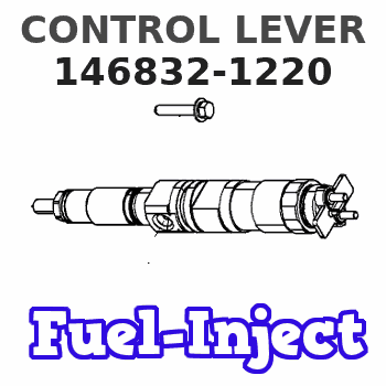
146832-1220
1468321220
ISUZU
8972102830
8972102830
Rating:
Include in ###:
Cross reference number
Zexel num
Bosch num
Firm num
Name
146832-1220
9 461 619 517
8972102830 ISUZU
CONTROL LEVER
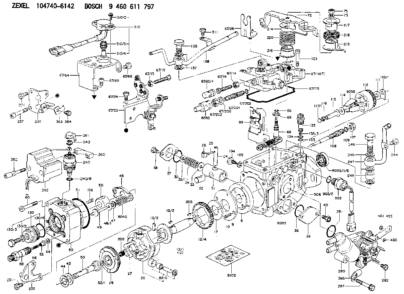
C 11FV LEVER parts(VE) Others
C 11FV LEVER parts(VE) Others
Information:
3. Remove nuts (1) and the bearing caps. Push the rods and pistons up until the rings are out of the cylinder liners. 4. Remove pistons (2) and connecting rod from the cylinder liners.5. Do Steps 1 through 4 for the remainder of the pistons.Install Pistons
1. Put clean engine oil on piston rings, connecting rod bearings and cylinder liners.
Never install the ring compressor on the piston unless the cylinder liner is used as a guide. Damage to the piston rings can be the result.
2. Use tool (A) and install pistons (1) and connecting rods in the cylinder liner. Be sure the number on the tab groove side of the connecting rod is on the opposite side from the camshaft.3. Install the bearing caps on the connecting rods with number on side of the bearing caps on the same side and same number as on the connecting rod.4. Install the nuts and tighten to a torque of 60 6 lb.ft. (80 8 N m). Put a mark on the nuts and caps and tighten nuts an extra 120°.5. Do Steps 1 through 4 for the remainder of the pistons.end by:a) install oil pumpb) install cylinder headDisassemble And Assemble Pistons
start by:a) remove pistons 1. Remove bearings (2) from the connecting rod and connecting rod cap.2. Remove retainer ring (1). Remove piston pin (3) from the piston and connecting rod. 3. Use tool (A) to remove the piston rings (4) from the piston. 4. Heat the connecting rod to a temperature of 350 to 500°F (177 to 260°C). Put connecting rod (6) in position on the base plate of tooling (B). Put a new bearing (5) on the adapter of tooling (B). Put the adapter in position in the connecting rod and base plate of tooling (B). 5. Install the pusher adapter (8) and pusher (7) from tooling (B) on the adapter. The old bearing is pushed out by tooling (B) as the new bearing is installed.6. Use tooling (B) to push the new bearing (5) into the connecting rod (6) until the push adapter of tooling (B) makes full contact with the connecting rod surface. See USE OF PISTON PIN BEARING REMOVAL AND INSTALLATION TOOLS, SPECIAL INSTRUCTION, Form No. SMHS7295. Use tooling (C) for later type connecting rods (tapered ends).7. Check the piston pin bore diameter after the bearing is installed. The correct dimension is 2.0012 .0003 in. (50.830 0.008 mm).8. Clean the ring grooves in the piston before rings are installed. The two compression rings have marks "UP-1" and "UP-2". The rings must be installed with these marks toward the top of the piston with "UP-1" as the top ring. After installation of all three piston rings, put piston rings in position so gaps in rings are 120° apart. 9. Use tool (A) to install the piston rings on the piston. 10. Install bearings (2) in the connecting rod and connecting rod cap. Be sure the tabs in back of bearings are in the tab
Have questions with 146832-1220?
Group cross 146832-1220 ZEXEL
Isuzu
146832-1220
9 461 619 517
8972102830
CONTROL LEVER