Information control lever
BOSCH
9 461 620 238
9461620238
ZEXEL
146832-0620
1468320620
NISSAN
16705VB504
16705vb504
Rating:
Include in ###:
Number on scheme 72B

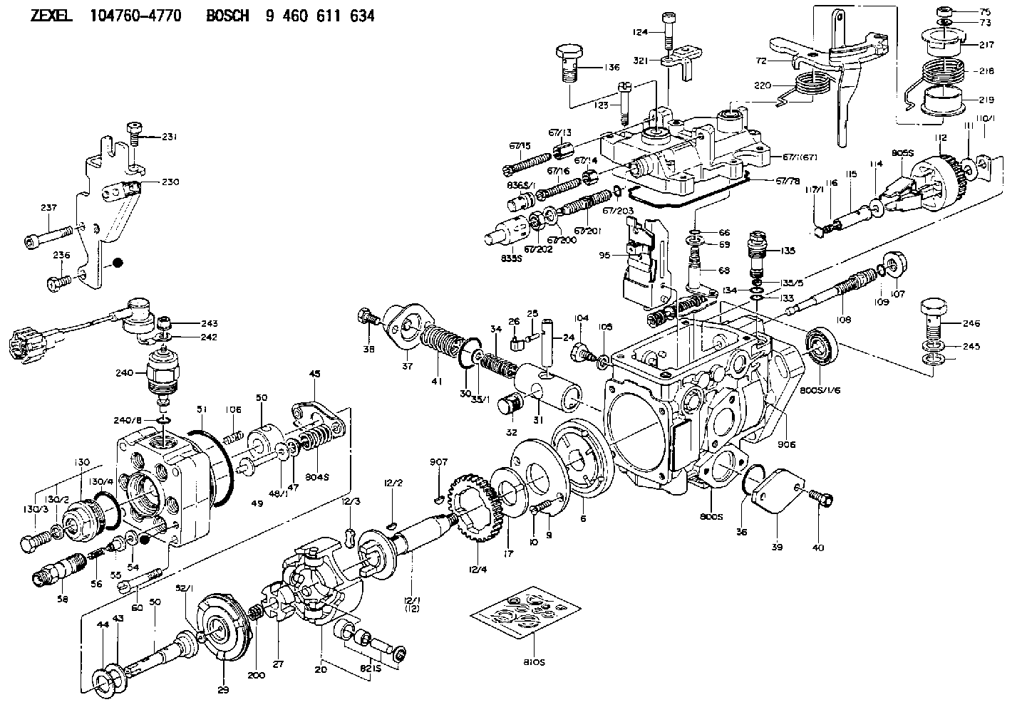
1047604770
as CONTROL LEVER
1047604960
as CONTROL LEVER
STAMP 206
1047604970
as CONTROL LEVER
1047607050
as CONTROL LEVER
STAMP 206
Cross reference number
Zexel num
Bosch num
Firm num
Name
146832-0620
9 461 620 238
16705VB504 NISSAN
CONTROL LEVER
C 11FV LEVER parts(VE) Others
C 11FV LEVER parts(VE) Others
146832-0620
9 461 620 238
16705VB504 NISSAN-DIESEL
CONTROL LEVER
C 11FV LEVER parts(VE) Others
C 11FV LEVER parts(VE) Others
Information:
1. Remove bolt (1) from the alternator and bracket. 2. Remove the two bolts that hold bracket (3) to the timing gear cover.3. Disconnect water line (2) from the air compressor. 4. Remove bolts (4) and (5) that hold the cylinder head to the cylinder block. 5. Fasten a hoist and remove cylinder head (6). The weight is approximately 300 lb. (135 kg).
Do not put the cylinder head down on a flat surface. This can cause damage to the fuel injection valves.
6. Remove the seals from the spacer plate.Install Cylinder Head Assembly
Be sure a new gasket has been installed between the spacer plate and the cylinder block. See REMOVE AND INSTALL SPACER PLATE. 1. Thoroughly clean the spacer plate and the bottom surface of the cylinder head. Install a new head gasket and new seals (1). Later model engines have two O-ring seals on top and bottom of the spacer plate. 2. Fasten a hoist and put cylinder head (2) in position on the cylinder block. 3. Put clean engine oil on the threads of the cylinder head bolts. Install the cylinder head bolts and washers. Tighten the bolts in sequence shown in illustration A87019x1: a) Tighten bolts 1 through 20 in number sequence to a torque of 200 20 lb.ft. (270 25 N m).b) Tighten bolts 1 through 20 in number sequence to a torque of 330 15 lb.ft. (450 20 N m).c) Tighten bolts 1 through 20 in number sequence to a torque of 330 15 lb.ft. (450 20 N m) by hand.d) Install rocker shafts and push rods. See INSTALL ROCKER SHAFTS AND PUSH RODS.e) Tighten bolts 21 through 26 in number sequence to a torque of 200 20 lb.ft. (270 25 N m).f) Tighten bolts 21 through 26 in number sequence to a torque of 330 15 lb.ft. (450 20 N m).g) Tighten bolts 21 through 26 in number sequence to a torque of 330 15 lb.ft. (450 20 N m) by hand.h) Tighten the 3/8" bolts to a torque of 32 5 lb. ft. (43 7 N m). If the studs for the exhaust manifold were removed, install new studs and tighten to 20 3 lb.ft. (25 4 N m).4. Make a adjustment to the valves to have a clearance of .015 (0.38 mm) for intake and .030 (0.76 mm) for exhaust. Install the valve cover bases and the inner fuel lines. Tighten the locknuts for the valve adjustment screws to a torque of 22 3 lb.ft. (28 4 N m).5. Install the valve cover bases and the inner fuel lines. See INSTALL ROCKER SHAFT AND PUSH RODS.6. Install the valve covers. See INSTALL VALVE COVERS. 7. Connect water line (3) to the air compressor. 8. Install bolt (4) for the alternator.end by:a) install exhaust manifoldb) install fuel injection linesc) install inlet manifoldd) install water temperature regulator
Have questions with 146832-0620?
Group cross 146832-0620 ZEXEL
Nissan
146832-0620
9 461 620 238
16705VB504
CONTROL LEVER
Nissan-Diesel
146832-0620
9 461 620 238
16705VB504
CONTROL LEVER