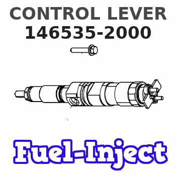
Information control lever
BOSCH
9 461 612 329
9461612329
ZEXEL
146535-2000
1465352000
ISUZU
8944430560
8944430560
Rating:
Include in ###:
Cross reference number
Zexel num
Bosch num
Firm num
Name
Information:
Removal Procedure for the Fuel Injection Pump
Table 1
Required Tools
Tool Part Number and Part Description Qty
A 267-2647 Stop Plug 1
B 9S-4180 Plug 1
Remove the air compressor. Refer to Disassembly and Assembly, "Air Compressor - Remove and Install".Note: Cleanliness is a critical factor. Before you begin the removal procedure, the exterior of the components should be thoroughly cleaned. This will help to prevent dirt from entering the internal mechanism.
Contact with high pressure fuel may cause personal injury or death. Wait 60 seconds after the engine has stopped to allow fuel pressure to purge before any service or repair is performed on the engine fuel lines.
Care must be taken to ensure that fluids are contained during performance of inspection, maintenance, testing, adjusting and repair of the product. Be prepared to collect the fluid with suitable containers before opening any compartment or disassembling any component containing fluids.Dispose of all fluids according to local regulations and mandates.
Keep all parts clean from contaminants.Contaminants may cause rapid wear and shortened component life.
Contact with high pressure fuel may cause fluid penetration and burn hazards. High pressure fuel spray may cause a fire hazard. Failure to follow these inspection, maintenance and service instructions may cause personal injury or death.
Ensure that the No. 1 cylinder is at the top center compression stroke. Refer to Testing and Adjusting, "Finding Top Center Position for No. 1 Piston".
Illustration 11 g01352511
Remove tube assembly (1), tube assembly (3), and tube assembly (4) .
Disconnect tube assembly (5) and tube assembly (6). Remove bolts (2) .
Remove Tooling (B) and install Tooling (A) .
Illustration 12 g01352571
Disconnect harness assemblies (8). Remove nuts (9) and the support assembly.
Remove bolts (10). Slide fuel injection pump (11) out of the front housing and disconnect hose assembly (7). Remove fuel injection pump (11) by pulling straight out of the front housing.Installation Procedure for the Fuel Injection Pump
Table 2
Required Tools
Tool Part Number and Part Description Qty
A 267-2647 Stop Plug 1
B 9S-4180 Plug 1
Keep all parts clean from contaminants.Contaminants may cause rapid wear and shortened component life.
Ensure that the No. 1 cylinder is at the top center compression stroke. Refer to Testing and Adjusting, "Finding Top Center Position for No. 1 Piston".
Illustration 13 g01352571
Note: Ensure that Tooling (A) is installed prior to installation of the fuel injection pump.
Align fuel injection pump (11) in the correct orientation relative to the front housing. Connect hose assembly (7) .
Install fuel injection pump (11). Move fuel injection pump (11) straight into the front housing in order to properly engage the gear. Install bolts (10) .
Install the support assembly and nuts (9). Connect harness assemblies (8) .
Illustration 14 g01352511
Remove Tooling (A) and install Tooling (B). Tighten Tooling (B) to a torque of 4.5 0.5 N m (40.0 4.0 lb in).
Install bolts (2). Connect tube assembly (6) and tube assembly (5)