Information control shaft
BOSCH
9 461 610 267
9461610267
ZEXEL
146515-0320
1465150320
ISUZU
8941748280
8941748280
Rating:
Compare Prices: .
As an associate, we earn commssions on qualifying purchases through the links below

Include in ###:
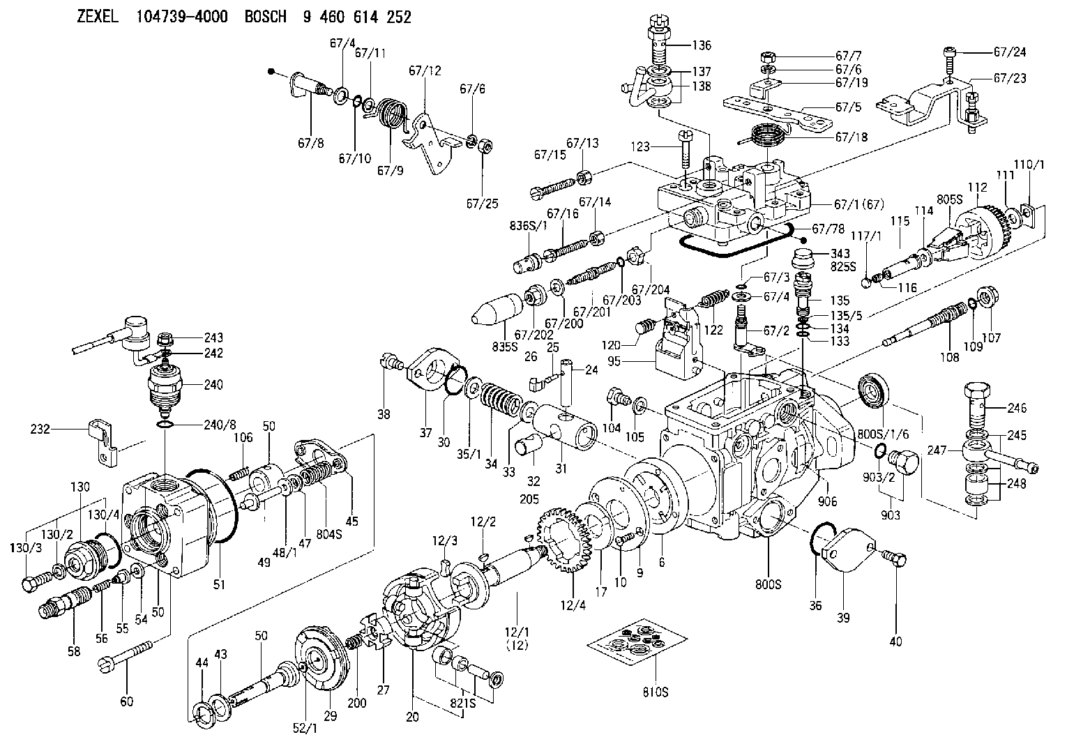
Number on scheme 67/2

1047394000
as CONTROL SHAFT
1047403612
as CONTROL SHAFT
R15.5
1047403613
as CONTROL SHAFT
1047403680
as CONTROL SHAFT
R15.5
1047403683
as CONTROL SHAFT
1047403690
as CONTROL SHAFT
R15.5
1047403693
as CONTROL SHAFT
1047403742
as CONTROL SHAFT
R15.5
1047403743
as CONTROL SHAFT
1047404460
as CONTROL SHAFT
R15.5
1047404462
as CONTROL SHAFT
1047404480
as CONTROL SHAFT
R15.5
1047404482
as CONTROL SHAFT
1047404740
as CONTROL SHAFT
R15.5
1047404741
as CONTROL SHAFT
Cross reference number
Zexel num
Bosch num
Firm num
Name
146515-0320
9 461 610 267
8941748280 ISUZU
CONTROL SHAFT
C 11FV CONTROL SHAFT parts(VE) Others
C 11FV CONTROL SHAFT parts(VE) Others
146515-0320
9 461 610 267
ME741811 MITSUBISHI
CONTROL SHAFT
C 11FV CONTROL SHAFT parts(VE) Others
C 11FV CONTROL SHAFT parts(VE) Others
146515-0320
9 461 610 267
19230R8100 NISSAN
CONTROL SHAFT
C 11FV CONTROL SHAFT parts(VE) Others
C 11FV CONTROL SHAFT parts(VE) Others
146515-0320
9 461 610 267
19312R8300 NISSAN
CONTROL SHAFT
A C 11FV CONTROL SHAFT parts(VE) Others
A C 11FV CONTROL SHAFT parts(VE) Others
146515-0320
9 461 610 267
19230R8100 NISSAN-DIESEL
CONTROL SHAFT
C 11FV CONTROL SHAFT parts(VE) Others
C 11FV CONTROL SHAFT parts(VE) Others
146515-0320
9 461 610 267
19312R8300 NISSAN-DIESEL
CONTROL SHAFT
A C 11FV CONTROL SHAFT parts(VE) Others
A C 11FV CONTROL SHAFT parts(VE) Others
146515-0320
9 461 610 267
1923010H00 NISSAN-DIESEL
CONTROL SHAFT
B C 11FV CONTROL SHAFT parts(VE) Others
B C 11FV CONTROL SHAFT parts(VE) Others
146515-0320
9 461 610 267
145624170 MAZDA
CONTROL SHAFT
C 11FV CONTROL SHAFT parts(VE) Others
C 11FV CONTROL SHAFT parts(VE) Others
Information:
Check Engine Light (Diagnostic) Output Circuit
The engine/vehicle harness provides information about the engine to the "check engine" light on the vehicle dash. The light flashes Diagnostic Code 34 when the ignition is ON and the engine is not running, to verify that the light works. When the engine is started the light will be ON solid until the PEEC system senses a minimum of 35 kPa (5 psi) oil pressure. If the engine light does not go out after the engine starts the light will begin to flash the Diagnostic Codes that are active in the PEEC System.The cruise ON/OFF and SET/RESUME switches can be used to interrogate the ECM for engine status. This is accomplished by placing the cruise ON/OFF switch in the OFF position and momentarily moving the Set/Resume switch to the RESUME position and then releasing it. The "check engine" light will emit a series of flashes which represent one or more, two digit numbers or diagnostic codes, which define engine status.An operating voltage of 12 Volts is supplied to the "check engine" light from the vehicle electrical system. The ECM turns on the light by connecting one side of the bulb to ground which completes the electrical circuit.Engine Electrical System
The electrical system can have three separate circuits: the charging circuit, the starting circuit and the low amperage circuit. Some of the electrical system components are used in more than one circuit. The battery (batteries), circuit breaker, ammeter, cables and wires from the battery are all common in each of the circuits.The charging circuit is in operation when the engine is running. An alternator makes electricity for the charging circuit. A voltage regulator in the circuit controls the electrical output to keep the battery at full charge.The starting circuit is in operation only when the start switch is activated.The low amperage circuit and the charging circuit are both connected through the ammeter. The starting circuit is not connected through the ammeter.Charging System Components
Alternator
The alternator is driven by V-type belts from the crankshaft pulley. This alternator is a three phase, self-rectifying charging unit, and the regulator is part of the alternator.This alternator design has no need for slip rings or brushes, and the only part that has movement is the rotor assembly. All conductors that carry current are stationary. The conductors are: the field winding, stator windings, six rectifying diodes, and the regulator circuit components.The rotor assembly has many magnetic poles like fingers with air space between each opposite pole. The poles have residual magnetism (like permanent magnets) that produce a small amount of magnet-like lines of force (magnetic field) between the poles. As the rotor assembly begins to turn between the field winding and the stator windings, a small amount of alternating current (AC) is produced in the stator windings from the small magnetic lines of force made by the residual magnetism of the poles. This AC current is changed to direct current (DC) when it passes through the diodes of the rectifier bridge. Most
Have questions with 146515-0320?
Group cross 146515-0320 ZEXEL
Isuzu
146515-0320
9 461 610 267
8941748280
CONTROL SHAFT
Mitsubishi
146515-0320
9 461 610 267
ME741811
CONTROL SHAFT
Nissan
146515-0320
9 461 610 267
19230R8100
CONTROL SHAFT
146515-0320
9 461 610 267
19312R8300
CONTROL SHAFT
Nissan-Diesel
146515-0320
9 461 610 267
19230R8100
CONTROL SHAFT
146515-0320
9 461 610 267
19312R8300
CONTROL SHAFT
146515-0320
9 461 610 267
1923010H00
CONTROL SHAFT
Mazda
146515-0320
9 461 610 267
145624170
CONTROL SHAFT