Information control sleeve
BOSCH
9 411 617 809
9411617809
ZEXEL
141241-7600
1412417600
NIIGATA
21484800
21484800
Rating:
Include in ###:
Cross reference number
Zexel num
Bosch num
Firm num
Name
141241-7600
9 411 617 809
21484800 NIIGATA
CONTROL SLEEVE
C 24XX CONTROL SLEEVE PF parts PF
C 24XX CONTROL SLEEVE PF parts PF
Information:
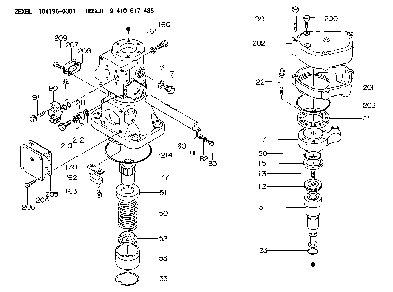
start by: a) remove fuel injection pumpsb) separation of governor from fuel injection pump housingc) remove fuel transfer pump1. Loosen the screws that hold the levers to the shaft assembly. 2. Remove the screw (1) that holds the lever assembly (2) to the shaft assembly. 3. Remove the shaft assembly (5) from the housing and remove the levers (3) and lever assembly (2).4. Loosen the screws that hold the levers (6) to the shaft.5. Remove the screw that holds the lever (4) to the shaft.6. Remove the shaft (7) from the housing and remove the levers. 7. Remove the lifter and roller assemblies (8) from the housing with a magnet. Put identification on the lifters (10) and rollers (9) for installation in their respective bores in the housing. 8. Remove the camshaft (11) from the housing.
Do not use a force to remove the camshaft. Turn the camshaft to permit the free passage of the camshaft by the bosses (12) in the housing.
Assemble Fuel Injection Pump Housing
1. Install the camshaft (1) in the housing.
Do not use a force to install the camshaft. Turn the camshaft to permit the free passage of the camshaft by the bosses in the housing.
2. Install the lifter and roller assemblies (2) in their respective bores in the housing with a magnet. Install the lifters with their grooves in alignment with the pins (3) in the housing. 3. Put the shaft (4) in the housing. Slide the levers (6) and the lever (5) on to the shaft in the order shown. Push the shaft into position in the housing. 4. Install the screw that holds the lever (5) to the shaft. Tighten the screw to a torque of 24 2 lb.in. (27.7 2.3 cm.kg). 5. Put the shaft assembly (7) in the housing. Slide the levers (9) and the lever assembly (8) on to the shaft in the order shown. Push the shaft assembly into position in the housing. 6. Install the screw that holds the lever assembly (8) to the shaft assembly. Tighten the screw to a torque of 24 2 lb. in. (27.7 2.3 cm.kg).end by: a) make adjustments to the sleeve control shafts (see TESTING AND ADJUSTING)b) install fuel transfer pumpc) connection of governor to fuel injection pump housingd) install fuel injection pumps
Have questions with 141241-7600?
Group cross 141241-7600 ZEXEL
Niigata
141241-7600
9 411 617 809
21484800
CONTROL SLEEVE